Transcription of Transformer Protection Application Guide
1 Transformer Protection Application Guide About the Author George Rockefeller is President of Rockefeller Associates, Inc. He has a BS in EE from Lehigh University, a MS from New Jersey Institute of Technology, and a MBA from Fairleigh Dickinson University. Mr. Rockefeller is a Fellow of IEEE and Past Chairman of IEEE Power Systems Relaying Committee. He holds nine Patents and is co-author of Applied Protective Relaying (1st Edition). Mr. Rockefeller worked for Westinghouse Electric Corporation for twenty-one years in Application and system design of protective relaying systems. He worked for Consolidated Edison Company for ten years as a System Engineer. He has also served as a private consultant since 1982. About the Guide This Guide contains a summary of information for the Protection of various types of electrical equipment. Neither Basler Electric Company nor anyone acting on its behalf makes any warranty or representation, express or implied, as to the accuracy or completeness of the information contained herein, nor assumes any responsibility or liability for the use or consequences of use of any of this information.
2 Original issue date 05/96. Revised 05/99, John Boyle; small updates Revised 08/03, Larry Lawhead; small updates Revised 04/07, John Horak; extensive rewrite Revised 06/07, John Horak; minor typographical and editorial corrections Transformer Protection Application Guide This Guide focuses primarily on Application of An overall view of the economic impact of a protective relays for the Protection of power Transformer failure and what can be done to transformers , with an emphasis on the most reduce the risk, including: prevalent Protection schemes and transformers . The direct economic impact of repairing Principles are emphasized. Setting procedures or replacing the Transformer . are only discussed in a general nature in the The indirect economic impact due to material to follow. Refer to specific instruction production loss. manuals for your relay. The references provide a Repair time vs. complete replacement source for additional theory and Application time. guidance. The availability of backup power feed or emergency replacement transformers , and The engineer must balance the expense of the cost of each option.
3 Applying a particular Protection scheme against The possibility that a given Protection the consequences of relying on other Protection scheme can reduce the damage and or sacrificing the Transformer . Allowing a pro- resultant repair time, or that it can change tracted fault would increase the damage to the a replacement into a repair. Transformer and the possibility of tank rupture with a consequent oil fire and consequent Some specific applications that affect Protection personnel safety risks. There is no rule that says are: A tap changer flashover can ordinarily be what specific Protection scheme is appropriate repaired in the field, but if this fault is allowed to for a given Transformer Application . There is evolve into a winding fault, the Transformer will some tendency to tie Protection schemes to the need to be shipped to a repair facility; hence, MVA and primary kV of a Transformer . While Protection that can rapidly sense a tap change there is some validity to this approach, there are fault is desirable.
4 A high magnitude through fault many other issues to be considered. Issues to (external fault fed by the Transformer ) shakes and be considered include: heats a Transformer winding, and the longer the through fault lasts, the greater the risk of it The severity of personnel safety concerns evolving into an internal Transformer fault; hence, and the possibility that a given Protection fast clearing for close-in external faults is part of scheme can reduce these risks. the Transformer Protection scheme. Some The danger to nearby structures and pro- transformers are considered disposable and cesses if a Transformer fails catastrophically readily replaced, reducing the need for ad- and the possibility that a given Protection vanced Protection schemes. Transformer protec- scheme can reduce the possibility of such a tion commonly includes some coverage of failure. 1. external bus and cable, and faults in these zones 2. Protection Example and General Concepts may expose personnel to arc flash hazards.
5 Slow The reader interested in additional information, clearing Protection schemes may be unaccept- advanced or unusual Application advice, and able from an arc flash exposure perspective. detailed settings guidance should refer to Ref. 1. Fires in an indoor Transformer may have high risk This document includes extensive references and of catastrophic facility damage and even higher bibliographies. Also, Ref. 2 and 3, textbooks on personnel safety risks, increasing the need for protective relaying, contain chapters on trans- advanced high speed Protection . The proximity former Protection , and Ref. 4, another IEEE. of flammable process chemicals increases a standard, includes good overall Protection need for Protection schemes that reduce the risk schemes where a Transformer is the interface of a tank fire. The failure of a Transformer used in point between a utility and an industrial customer. a large base load unit-connected generator may cause extended generation-replacement costs; There are three general categories of protective even the loss of a small station service trans- relay technology that arise in the discussions to former can cause a notable disruption of genera- follow: tion and high economic consequences.
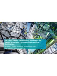
6 Similar Electromechanical: uses magnetic flux economic impacts may also exist at industrial created from current and voltage to create sites. Some transformers are custom designs torques on movable disks and relays, which that may have long lead times, increasing the is the source of the term relay. Usually need for advanced Protection schemes. single device number functionality. Solid State: uses low voltage analog signals 1. Failure Statistics created from sensed currents and voltages;. uses discrete electronics and basic logic Table I lists failures for six categories of faults circuits; may contain a basic microprocessor (IEEE , Guide for Protective Relay for logic and some math. Usually single or Applications to Power transformers , Ref. 1). dual device number functionality. Winding and tap changers account for 70% of Numeric: a multifunction, programmable failures. Loose connections are included as the logic relay; digitizes sensed current and initiating event, as well as insulation failures.
7 The voltage, then calculates an RMS or phasor miscellaneous category includes CT failure, equivalent value; uses a high-end micropro- external faults, overloads, and damage in cessor. Usually incorporates many device shipment. An undisclosed number of failures number functions. starts as incipient insulation breakdown prob- All Basler Electric relays are solid state or lems. These failures can be detected by sophis- numeric. ticated online monitoring devices ( gas-in-oil analyzer) before a serious event occurs. 1955-1965 1975-1982 1983-1988. Percent of Percent of Percent of Number Total Number Total Number Total Winding failures 134 51 615 55 144 37. Tap changer failures 49 19 231 21 85 22. Bushing failures 41 15 114 10 42 11. Terminal board failures 19 7 71 6 13 3. Core failures 7 3 24 2 4 1. Miscellaneous failures 12 5 72 6 101 26. TOTAL 262 100 1127 100 389 100. Table I - Failure Rates, Ref. 1. 2. Table II lists some common ANSI device num- bers associated with Transformer Protection .
8 A If there is a possibility of over voltage on the numeric relay generally contains many imple- units due to local generation or a Transformer mentations of these devices within its program- being placed at the end of a long line (the ming, and each instance of a device is referred Feranti effect), voltage relays (24 and 59, to, herein, as an element in the relay. For Section ) may be included. Another pos- example, while the Basler BE1-CDS220 is sible backup Protection scheme is low voltage primarily a Transformer differential relay (hence, (27) or unbalanced voltage detection (47). If includes the 87 device in elements named 87P there is local generation, to help detect and 87N), it also includes nine independent islanding conditions an over/under frequency implementations of the 51 overcurrent device, (81, O/U) relay may be installed, though an 81. called the 51P, 151P, 251P, 51Q, 151Q, 251Q, may not be considered a Transformer Protection 51N, 151N, and 251N elements as well as many element.
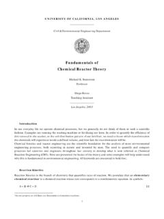
9 Other device functions. Directional overcurrent relays and directional Figure 1 shows extensive use of relays that power (67/50, 67/51, and 32, respectively, would be representative of a large industrial Section ) respond to load current circulating load. This will be used for discussions in some of through the 13 kV buses when the 115kV. the material that follows. There are two 115 kV breaker A is open and the tie is closed. feeds to two 30 MVA transformers that are The elements may also respond to faults in the resistance grounded on the 13 kV side, limiting Transformer near the secondary bushings. If the ground fault current to about 400A from each transformers can be operated in parallel, the Transformer . In other applications, a reactor is elements also provide a means to sense tap used, and in some applications, the ground fault changers that have become out of step with one current is limited to less than 10A. In a typical another. If there is generation in the utility Application , transformers are connected system, sensitive 67 elements can sense a small directly to ground, but occasionally a small generator backfeeding a 115kV fault.
10 Reactor is placed in the Transformer neutral that limits ground fault current to approximately the The primary and secondary relaying would same level as three phase faults. In this example sometimes be configured to feed their own system, the Protection scheme described lockout relays (86) to help ensure that Protection applies to solidly grounded (as well as imped- is available even with a failure of one 86 relay or ance grounded) systems, except the effect of its dc feed. ground impedance results in the addition of Protection functions not required on a solidly The Protection scheme in does not utilize grounded system. fuses. Fuses normally would be seen only on lower MVA transformers than indicated. See The phase and ground differential (87P and 87N, Section 3. Section 4) and sudden pressure relay (63, Section 6) provide the primary Transformer fault transformers of the indicated MVA normally Protection . The suite of overcurrent elements would have their oil tested for dissolved gasses (51, Section 8) is generally considered backup (Section 7) as part of routine maintenance.