Transcription of Transformers
1 Transformers Contents Page Introduction .. 5/2. Product Range .. 5/3. Electrical Design .. 5/4. Transformer Loss Evaluation .. 5/6. Mechanical Design .. 5/8. Connection Systems .. 5/9. Accessories and Protective Devices .. 5/11. Technical Data Distribution Transformers .. 5/13. Technical Data Power Transformers .. 5/18. On-load Tap Changers .. 5/26. Cast-resin Dry-type Transformers , GEAFOL .. 5/27. Technical Data GEAFOL Cast-resin Dry-type Transformers .. 5/31. Special Transformers .. 5/35. 5. Ohne Namen-1 1 , 16:22 Uhr Introduction Transformers are one of the primary In addition, there are various special- Standards and specifications, general components for the transmission and purpose Transformers such as converter The Transformers comply with the relevant 1 distribution of electrical energy.
2 Transformers , which can be both in the VDE specifications, DIN VDE 0532. Their design results mainly from the range range of power Transformers and in the Transformers and reactors and the of application, the construction, the rated range of distribution Transformers as far Technical conditions of supply for three- power and the voltage level. as rated power and rated voltage are con- phase Transformers issued by VDEW. The scope of transformer types starts with cerned. and ZVEI. 2 generator Transformers and ends with dis- As special elements for network stabili- Therefore they also satisfy the require- tribution Transformers . zation, arc-suppression coils and com- ments of IEC Publication 76, Parts 1 to 5.
3 Transformers which are directly connected pensating reactors are available. Arc-sup- together with the standards and specifi- to the generator of the power station are pression coils compensate the capacitive cations (HD and EN) of the European called generator Transformers . Their power current flowing through a ground fault and Union (EU). range goes up to far above 1000 MVA. thus guarantee uninterrupted energy sup- 3 Their voltage range extends to approx. ply. Compensating reactors compensate Enquiries should be directed to the manu- 1500 kV. the capacitive power of the cable networks facturer where other standards and spe- and reduce overvoltages in case of load cifications are concerned.
4 Only the US. The connection between the different high- rejection; the economic efficiency and (ANSI/NEMA) and Canadian (CSA) stand- voltage system levels is made via network stablility of the power transmission are im- ards differ from IEC by any substantial de- Transformers (network interconnecting proved. gree. A design according to these stand- 4 Transformers ). Their power range exceeds ards is also possible. 1000 MVA. The voltage range exceeds The general overview of our manufactur- 1500 kV. ing/delivery program is shown in the Distribution Transformers are within the table Product Range . Important additional standards range from 50 to 2500 kVA and max.
5 DIN 42 500, HD 428: oil-immersed 36 kV. In the last step, they distribute three-phase distribution Transformers 5 the electrical energy to the consumers Rated Max. Figs. 50 2500 kVA. by feeding from the high-voltage into the power operating on DIN 42 504: oil-immersed three-phase low-voltage distribution network. These voltage page Transformers 2 10 MVA. are designed either as liquid-filled or as [MVA] [kV] DIN 42 508: oil-immersed three-phase dry-type Transformers . Transformers 80 MVA. 6 Transformers with a rated power up to DIN 42 523, HD 538: three-phase MVA and a voltage up to 36 kV are Oil 36 5/13 dry-type Transformers 100 2500 kVA.
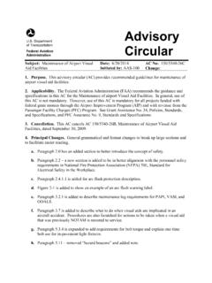
6 Referred to as distribution Transformers ; distribution 5/17 DIN 45 635 T30: noise level all Transformers of higher ratings are Transformers classified as power Transformers . IEC 289: reactance coils and neutral grounding Transformers Power 3000 36 1500 5/18 . 7 Transformers 5/25 IEC 551: measurement of noise level IEC 726: dry-type Transformers GEAFOL- 20 36 5/27 RAL: coating/varnish cast-resin 5/34. Transformers 8. Fig. 1: Transformer types 9. 10. 5/2 Siemens Power Engineering Guide Transmission and Distribution 4th Edition Ohne Namen-1 2 , 16:23 Uhr Product Range Oil-immersed 50 to 2 500 kVA, highest voltage for equipment up to 36 kV, distribution Transformers , with copper or aluminum windings, hermetically sealed (TUMETIC ) or 1.
7 TUMETIC, TUNORMA with conservator (TUNORMA ) of three- or single-phase design 2. Generator and power Above MVA up to more than 1000 MVA, above 30 kV up to 1500 kV. Transformers (system and system interconnecting Transformers , with separate windings or auto-connected), with on-load tap changers or off-circuit tap changers, of three- or single-phase design 3. Cast-resin distribution 100 kVA to more than 20 MVA, highest voltage for equipment up to 36 kV, and power Transformers of three- or single-phase design GEAFOL GEAFOL -SL substations 4. 5. Special Transformers Furnace and converter Transformers for industry, traction Traction Transformers mounted on rolling stock and appropriate on-load tap-changers and HVDC transmission Substation Transformers for traction systems systems Transformers for train heating and point heating Transformers for HVDC transmission systems 6.
8 Transformers for audio frequencies in power supply systems Three-phase neutral electromagnetic couplers and grounding Transformers Ignition Transformers 7. Reactors Liquid-immersed shunt and current-limiting reactors up to the highest rated powers Reactors for HVDC transmission systems 8. Accessories Buchholz relays, oil testing equipment, oil flow indicators and other monitoring devices 9. Fan control cabinets, control cabinets for parallel operation and automatic voltage control Sensors (PTC, Pt 100). 10. Service Advisory services for transformer specifications Organization, coordination and supervision of transportation Supervision of assembly and commissioning Service/inspection troubleshooting services Training of customer personnel Investigation and assessment of oil problems Fig.
9 2. Siemens Power Engineering Guide Transmission and Distribution 4th Edition 5/3. Ohne Namen-1 3 , 16:23 Uhr Electrical Design Power ratings and type of cooling All power ratings in this guide are the pro- 1 duct of rated voltage (times phase-factor I. for three-phase Transformers ) and rated Dy1 1 Yd1 I. current of the line side winding (at center tap, if several taps are provided), expres- 1. iii i sed in kVA or MVA, as defined in IEC 76-1. iii i 2 If only one power rating and no cooling III ii II. method are shown, natural oil-air cooling III ii II. (ONAN or OA) is implied for oil-immersed Transformers . If two ratings are shown, forced-air cooling (ONAF or FA) in one or two steps is applicable.
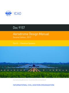
10 I. Dy5 Yd5 I. 3 For cast resin Transformers , natural air cooling (AN) is standard. Forced air cooling ii iii iii (AF) is also applicable. ii III i II. 5 III i II. Temperature rise 4 5. In accordance with IEC-76 the standard temperature rise for oil-immersed power 11. and distribution Transformers is: Dy11 I Yd11 I. 65 K average winding temperature 11. (measured by the resistance method) i 5 60 K top oil temperature ii i iii ii (measured by thermometer) III II. III iii II. The standard temperature rise for Siemens cast-resin Transformers is 100 K (insulation class F) at HV and 6 LV winding. Fig. 3: Most commonly used vector groups Whereby the standard ambient tempera- tures are defined as follows: 40 C maximum temperature, 2% increase for every 500 m altitude (or The primary winding (HV) is normally 30 C average on any one day, part there of) in excess of 1000 m, or connected in delta, the secondary winding 7 20 C average in any one year, 2% reduction of rated power for each (LV) in wye.