Transcription of Transient response of RC and RL circuits
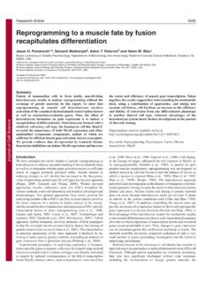
1 Transient response of RC and RL circuitsENGR 40M lecture notes July 26, 2017 Chuan-Zheng Lee, Stanford UniversityResistor capacitor (RC) and resistor inductor (RL) circuits are the two types offirst-ordercircuits: circuitseither one capacitor or one inductor. In many applications, these circuits respond to asudden changein aninput: for example, a switch opening or closing, or a digital input switching from low to high. Just after thechange, the capacitor or inductor takes some time to charge or discharge, and eventually settles on its newsteady state. We call the response of a circuit immediately after a sudden change thetransient response , incontrast to the steady first exampleConsider the following circuit, whose voltage source providesvin(t) = 0 fort <0, andvin(t) = 10 V fort 0.
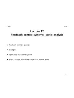
2 +vin(t)RC+ voutA few observations, using steady state beforethe step invinfrom 0 V to 10 V att= 0,vout(0 ) = 0 V. Sincevoutis across a capacitor,voutjust afterthe step must be the same:vout(0+) = 0 afterthe step, if we wait long enough the circuit will reach steady state, thenvout( ) = 10 happens in between? Using Kirchoff s current law applied at the top-right node, we could write10 V voutR= this differential equation, then applying the initial conditions we found above, would yield (in volts)vout(t) = 10 10e tRC. =RC2 3 4 510vout(t)vin(t)tvWhat s happening? Immediately after the step, the current flowing through the resistor and hence thecapacitor (by KCL) isi(0+) =10 VR.
3 Sincei=Cdvoutdt, this current causesvoutto start rising. This, inturn,reducesthe current through the resistor (and capacitor),10 V voutR. Thus, the rate of change ofvoutdecreases asvoutincreases. The voltagevout(t) technically never reaches steady state, but after about 3RC,it s very response equationIt turns out thatallfirst-order circuits respond to a sudden change in input with some sort of exponentialdecay, similar to the above. Therefore, we don t solve differential equations every time we see a capacitor oran inductor, and we won t ask you to solve , we use the following shortcut: In any first-order circuit, if there is a sudden change att= 0, thetransient response for a voltage is given byv(t) =v( ) + [v(0+) v( )]e t/ ,wherev( ) is the (new) steady-state voltage;v(0+) is the voltage justaftertimet= 0; is thetimeconstant, given by =RCfor a capacitor or =L/Rfor an inductor, and in both casesRis theresistanceseen by the capacitor or Transient response for a current is the same, withi( ) instead ofv( ):i(t) =i( ) + [i(0+) i( )]e t/.
4 What do we mean by the resistance seen by the capacitor/inductor ? Informally, it means the resistanceyou would think the rest of the circuit had, if you were the capacitor/inductor. More precisely, you find itusing these steps:1. Zero out all sources ( all voltage sources, open all current sources)2. Remove the capacitor or inductor3. Find the resistance of the resistor network whose terminals are where the capacitor/inductor wasAbout the time constantThe time constant (the Greek lettertau) has units of seconds (verify, for bothRCandR/L), and itgoverns the speed of the Transient response . circuits with higher take longer to get close to the newsteady state.
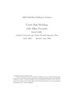
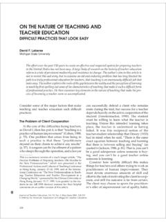
5 circuits with short settle on their new steady state very precisely, every time constant , the circuit gets 1 e 1 63% of its way closer to its new steadystate. Memorizing this fact can help you draw graphs involving exponential decays 3 , the circuit will have gotten 1 e 3 95% of the way, and after 5 , more than 99%. So, after afew time constants, for practical purposes, the circuit has reached steady state. Thus, the time constant isitself a good rough guide to how long the Transient response will course, mathematically, the steady state is actually an asymptote: it nevertrulyreaches steady , unlike mathematicians, engineers don t sweat over such inconsequential details.
6 2 3 4 5 v( )v(0+) 63% of[v(0+) v( )] 95% of[v(0+) v( )]tv(t)2 Examples and exercisesExample the first-order Transient response equation to verify the result forvout(t) that was foundin theRCexample on page 1.[Not examinable material.]In the following circuit, the switch closes at timet= 0, beforewhich it had been open for a long time. Use Kirchoff s voltage law to write a differential equation for thefollowing circuit, and solve it to findvout(t). Verify that your answer matches what you would get fromusing the first-order Transient response equation. +10 Vt= 0 RLiL+ voutExample the above circuit (the same as for Exercise 1), the switch closes at timet= 0, before whichit had been open for a long time.
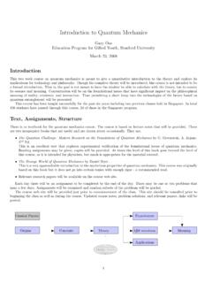
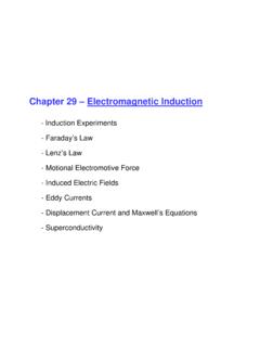
7 (a) Find and plotiL(t).(b) Find and plotvout(t).Example the below circuit,vin(t) is as is shown in the plot. (For all times outside the plot,vin(t) =0 V.) Find and plotvout(t), fort > (ms)vin(t) (V) +5 V20 k 330 nF+ vout20 k +vin(t)Example the below circuit, the switch has been closed for a long time beforet= 0. The switch thenopensatt= 0, and thenclosesatt= 100 s. Find and plotvout(t). +10 V100 100 + vout1 mH3 Solution to Example 3 Whent <10 (t) = 0, the NMOS transistor is off, so the circuit reduces to this: +5 V20 k 330 nF+ vout20 k Sincevin(t) = 0 for allt <10 ms, the circuit is in steady state att= 10 ms . Furthermore, that 20 k resistor on the right doesn t do anything while the transistor is off.
8 So the circuit reduces to this: +5 V20 k + voutfrom which we see thatvout(t) = 5 V at steady state while the transistor is off, including whent <10 10 ms< t <20 this period,vin(t) = 5 V, so the transistor is on (vGS= 5 V 0 V = 5 V).Then we have this circuit: +5 V20 k 330 nF+ vout20 k The voltagevoutis the voltage across a capacitor, which can t change instantaneously, sovout(10 ms+) =vout(10 ms ) = 5 V. (Caution! The logic isn t that theoutput voltagecan t change instantaneously, it s thethe voltageacross the capacitorcan t.)To find thev( ) term of the equation, for this part, we find the steady state value of the circuit while thetransistor is on in other words, the value thatvout(t)wouldconverge to if the transistor stayed on forever.
9 (The circuit can t predict the future, so it doesn t know that the transistor will turn off soon.) To find thesteady state value, we replace the capacitor with an open circuit again:4 +5 V20 k + vout20 k Now we can see that there is just a voltage divider, andvout( ) in this statewould time constant is =RC, whereRis the resistance seen by the capacitor. To find this, we short (zero)the voltage source and imagine measuring the resistance from the capacitor:20 k 20 k capacitorwas hereAnd now we can see that it s just two 20 k resistors in parallel, yieldingR= 10 k . Then =RC= 10 k 330 nF = it all together, for 10 ms< t <20 ms:vout(t) =vout( ) + [vout(10 ms+) vout( )]e t 10 ms = + [5 ]e t 10 ms(V)= + t 10 ms(V)Whent >20 , the transistor has turned off again.
10 Because the voltage across the capacitor can tchange instantaneously,vout(20 ms+) =vout(20 ms ), andvout(20 ms ) falls into the equation we just found:vout(20 ms ) = + 20 ms 10 ms= ( ) term is just the steady state when the transistor is off, which we ve already found above; it was5 for the time constant, if we short the voltage source and remove the capacitor while the transistor is off,we get this:20 k capacitorwas here20 k 5 That resistor on the right isn t really part of the circuit, so really we just have this:20 k capacitorwas hereAnd now it s clear thatR= 20 k . Then =RC= 20 k 330 nF = that this is twice as long as the time constant while the transistor was it all together, fort >20 ms:vout(t) =vout( ) + [vout(20 ms+) vout( )]e t 20 ms = 5 + [ 5]e t 20 ms(V)= 5 t 10 ms(V)Here is a plot, withvin(t) drawn underneath for ease of reference.