Transcription of Transistor Basics - Ted Pavlic
1 Transistor BasicsLab 1: The bipolar ( junction ) TransistorECE 327:Electronic Devices and Circuits Laboratory IAbstractIn the lab, we explore several common Transistor circuits; we build a common-emitter amplifier, apnpcurrent source, annpnemitter follower, and class B and class AB ( , biased) push pull , we introduce basic operating guidelines for bipolar transistors and outlines of these bipolar junction Transistor Model22 The Ideal bipolar junction Transistor3 Saturation Mode and Compliance.. 33 Common-Emitter Amplifier44pnpCurrent Sources55pnpCurrent Mirror66npnEmitter Follower77 Simple Class-B Push Pull Amplifier88 Biased Class-B Push Pull Amplifier9A Bootstrapping for Higher Input Impedance10B Parts11 Note about diode/bandgap conventions:We use the convention that a typical silicon BJT base emitter diode drop is V and a standard general purpose silicon diode drop is V. Other conventionsuse V or V for one or both.
2 Measured laboratory results will most likely be between these two and BJTs implemented on the sameintegrated circuit( , on the same piece of silicon) mayhave equivalent characteristics. That is, the diodes and transistors can bematched. Matched componentsare convenient to use in many circuit designs. We usediscreteelements in this laboratory, and so it isnot possible to match components unless they re all implemented within the one part. In the laboratory, a diode-connected Transistor ( , shorted base and collector) may match the base emitter characteristicsof another Transistor better than a drops are strongly temperature dependent. Room-temperature transistors have base emitter dropsaround V, but hot transistors have drops near V because they need less excitation for conduction. Sotemperature matching is just as important as component matching. Internal temperature compensation in bandgap voltage references lets them provide a temperature-independent voltage reference.
3 Their outputreference of V is the Silicon diode drop at absolute zero ( , 0 K or C). It is not a coincidencethat the Silicon bandgap ( , the energy separating valence and conduction electron bands) is dependence and manufacturing variations (andthe Early effect ) are always a 2007 2009 by Theodore P. PavlicCreative Commons Attribution-Noncommercial LicensePage 1 of 11 ECE 327 [ lab 1 : The bipolar ( junction ) Transistor ] Transistor Basics1 bipolar junction Transistor ModelA bipolar junction Transistor (BJT) can be in three modes:cutoff mode: Transistor acts like anopen switchbetween collector and emitter ( ,collector emitter resistance is infinite).active mode: Transistor acts like adynamic resistorbetween collector and emitter thatadjusts its resistance in order to keep collector current ata set level ( ,collector emitter resistance is finite and positive).saturation mode: Transistor acts like aclosed switchbetween collector and emitter ( ,collector emitter resistance is very low).
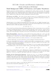
4 Trivial switch modesIn theactive mode, the Transistor adjusts thecollectorcurrent to be a version of thebasecurrent amplifiedby some constant >0. If the base current falls to 0, the Transistor enterscutoff modeand shuts off. Whenthe base current rises too far, the Transistor loses its ability to decrease the collector emitter resistanceto linearly increase the collector current. In this case, the Transistor enterssaturation mode. To keep thetransistor out of saturation mode, the collector and emitter should be separated by at least simple model for the operation of a Transistor inactive modeis shown inFigure It requires knowingthe current gain in order to design the circuit. In both of these models,iC= iBandiE= ( + 1)iB,and the emitter is separated from the base by a diode. In orderfor this diode to conduct current, it mustbe forward biased with iBiE=iB+iC= ( + 1)iB VPN vBvC> vE+ VvE=vB ViC= iB(a) Active iBiE=iB+iC= ( + 1)iB VPN vBvE=vB+ VvC< vE ViC= iB(b) Active : Simple models of active mode bipolar junction transistors (BJTs).
5 1 This is approximate. In general, the value will be between V and V, and may rise to V in saturation 2007 2009 by Theodore P. PavlicCreative Commons Attribution-Noncommercial LicensePage 2 of 11 ECE 327 [ lab 1 : The bipolar ( junction ) Transistor ] Transistor Basics2 The Ideal bipolar junction TransistorBecause the current gain is typically unknown or varies greatly with temperature, time, collector emitterpotential, and other factors, good designs should not depend on it. In this laboratory, we assume that issufficiently large ( , 1, where 100 in our laboratory) so thatiB 0andiC simple rules are similar to the rules we use with operational amplifiers. The analysis approach usuallyfollows these steps:1. Calculate the Transistor base potentialvBby assuming that no current enters the base ( ,iB 0).2. Calculate the potentialvEat the emitter of the Transistor usingvB. For annpntransistor,vE=vB V,and for apnptransistor,vE=vB+ Calculate the emitter currentiEusing the emitter voltagevEand the rest of the Assume thatiC iEand analyze the rest of the circuit.
6 Because we knowvE, we usually knowiEas well. So ouriEdictates whatiCshould , keep these notes in mind. For annpntransistor, active mode requiresvC vE> V. For apnptransistor, active moderequiresvE vC> V. If this condition is violated, the Transistor is saturated, and the analysiscannot continue using these simple rules. Indesignproblems, change parameters ( , resistors, supplyrails, etc.) to prevent saturation. Sometimes it s easier to findvEfirst and use it to calculatevB. How small iBmust be to neglect its effect depends on the circuit. In particular,iB RBmust bevery small, whereRBis the the Th evenin equivalent resistance lookingoutof the Transistor Base-Emitter Diode:Always keepFigure mind. TheEbers-Moll modelof aBJTtreats thecurrent-voltage relationship of the base emitter junction just like aShockley ideal diodewhos current ismirrored by the collector with gain . WhenvBandvEare not obvious, remember the base Mode and ComplianceThese simple rules are only valid when the Transistor is inactive mode.
7 In this mode, the Transistor is able todynamically adjust its collector emitter resistance fromnear 0 ( , a closed switch with some small finiteresistance) to ( , an open switch). These simple rules fail when they imply that the collector emitterresistance isnegative( , when they imply that the Transistor is acting like a battery). When the collector emitter potential in annpntransistor drops to below V, the transistorsaturatesand leaves active mode. When the emitter collector potential in apnptransistor drops to below V, the transistorsaturatesand leaves active nearly every design in this laboratory, we will keep the transistors inactive mode. The only exceptionto this is when we use the Transistor as aswitch. For theswitchcase, the Transistor base current is madesufficiently high to drive it into saturation, which brings its collector emitter potential as close to 0 :A circuit scompliancerefers to the output voltages possible that keep its active components( , its transistors) all in their active modes.
8 If the output voltage is outside of the compliance range, thedevice will not operate correctly ( , a current source will stop providing constant current).Copyrightc 2007 2009 by Theodore P. PavlicCreative Commons Attribution-Noncommercial LicensePage 3 of 11 ECE 327 [ lab 1 : The bipolar ( junction ) Transistor ] Transistor Basics3 Common-Emitter AmplifierAnnpncommon-emitter amplifier (withemitter degeneration) is shown inFigure some timet +vin(t)VinRCRE12 V12 V0 V0 V0 VCBE+vEC vEC(t)> VvE(t) =vB(t) VlimT 1T T0vin(t) dt= 0 VvB(t) vin(t) +R2R1+R2(12 V)andvB(t)> Vvout(t)vout(t) = (12 V) vE(t)RERC andvout(t)> vE(t) + VInput isVin+vin(t)(DC & AC parts)Key assumptions (R1kR2)Cis large(but preferC 1 F) (R1kR2) RE( 100) RCis not extremely large(preferRC 300 k )Figure : Single-endednpncommon-emitter amplifier (a level-shifter amplifier).From theboxed expressions inFigure , it should be clear that at any timet,vout(t) = (12 V) + ( V)RCRE RCRER2R1+R2(12 V) DC offset of output signal RCRE |Gain|vin(t).
9 ( )Pay attention to the inequalities; they keep the transistorout of cutoff and saturation modes. So( V) R2R1+R2(12 V)<mint{vin}and maxt{vin}<( V)RERE+RC (12 V)R2R1+R2+ ( V).( )For maximal bandwidth and minimal current draw, it s best tomakeR1andR2as large as , to keep the circuit as insensitive to variations in as possible,make sure that(R1kR2) REwhereR1kR2,R1R2R1+R2and 100.( )That is, keep the parallel combinationR1kR2less than the approximate input impedance of the , even a small base current will cause a significantdrop capacitorCis needed to AC couple the signal to the base of the Transistor . In particular,C,R1, andR2form a high-pass filter with single time constant (R1kR2)C, and soC 0. Iffis the lowest frequency ofinterest in the input ( , all signals reach the amplifier with at least half power above this frequency), thenC 12 f(R1kR2)whereR1kR2,R1R2R1+R2.( )At signal frequencies, the circuit s input impedance may bevery low.
10 If the circuitloadsthe input source( , input signal amplitude drops when connected to your circuit) and you cannot increaseR1andR2anymore, then try the configuration discussed inAppendix output impedance of this circuit can be prohibitively high. Its use often necessitates also using abuffer like the one insection 6. To prevent attenuation or low-pass effects, keepRClow ( ,RC 300 k ).Copyrightc 2007 2009 by Theodore P. PavlicCreative Commons Attribution-Noncommercial LicensePage 4 of 11 ECE 327 [ lab 1 : The bipolar ( junction ) Transistor ] Transistor Basics4pnpCurrent SourcesForFigure , pickvBandREfor currentiout. Device in compliance whenvRE LRE< vcomp< Use givenvcompto UsevREand givenioutto V12 V0 V0 VEBC+vCE vCE> VAssuming thatR1kR2 RE,thenvB R2R1+R2(12 V).For compliancevcomp< V,setvBso thatvcomp V< vB< +vRE vRE V vBFigure : Resistor-biasedpnpcurrent source outputiout,vcompcompliance, , pickvBfor currentiout.