Transcription of Transmission Line Fundamentals by - Chris Angove
1 Transmission Lines Page1 of 215 May 2011 Transmission LineFundamentalsbyChris AngoveDISCLAIMERThe Author makes no representation or warranties with respect to the accuracy orcompleteness of the contents of this paper and specifically disclaims any impliedwarranties of merchantability or fitness for any particular purpose and shall in no event beliable for any loss of profit or any other commercial damage, including but not limited tospecial, incidental, consequential or other opinions expressed are thosepersonal opinions ofthe Author onlyand they do not necessarily imply that any detailedand accredited engineering tests have been performed to arrive at reader is advised to check the information given, formulas and derivations againstother sources before using them because the Author cannot guarantee them to be Lines Page2 of 215 May 2011 AccronymMeaning mmicrometerdBdecibelDCdirect currentRFradio frequencyTEtransverse electricTEMtransverse electric magneticTMtransverse magneticVSWR voltage standing wave ratioTransmission Lines Page3 of 215 May 2011 Contents1 Transmission is an Electrical Transmission line ?
2 Elements of a Practical Uniform TEM Transmission Total Voltage Total Current Reflection Coefficient, Voltage Standing Wave Ratio and Return Variation of Impedance Along a Practical (Lossy) Mismatched Transmission Loss-Free Transmission Loss-Free Transmission line Constant and Phase Rectangular Waveguide [2]133 References21 FiguresFigure 1-1 The fundamental element section of a uniform TEM Transmission 1-2 The fundamental Transmission line 2-1 The rectangular co-ordinate system used with rectangular Lines Page4 of 215 May 20111 Transmission is an ElectricalTransmission line ?An electricaltransmission line is a devicefor transferring electrical energy from onelocation to another. This must usually be achieved with the highest possible lines have been developed for operation atpracticallyallfrequencies fromDCto optical.
3 There are threecommontypes of Transmission line used in radio frequency(RF)and microwave engineering: Transverse electric-magnetic (TEM) Transmission lines. Conductor waveguides. Dielectric Transmission lineshave separate conductors for the forward and return electriccurrent paths andinclude open wirelines, twisted wirelines, coaxial common Transmission line known as microstripdeparts slightly from pure TEMas thefield associated with the line is shared between the substrate materialandtheair above,sothis line is sometimescalleda quasi-TEMtransmission line . A TEM Transmission linewill operate at frequencies from DC upwards. Inpracticehowever, there isan upperfrequencylimitdetermined bywhenthewavelength becomes sufficiently short thatnon-TEM modes start to are known as waveguide modesand comprise eithertransverse electric (TE) or transverse magnetic (TM) waveguidestake the form ofprecision rigidpipescomprisinginsulator coresbound by electrical conductors.
4 Theyallow propagation of electrical energy in the form ofnon-TEM wavemodessupportedby electrical currents circulating on the inside walls ofthe guide andthe resulting magnetic and electric modes are again specificorders of TE or TM waveguides comprise cores of low loss dielectric material surrounded by a shellof anothersimilardielectric materialbut witha slightly higher dielectric occurs by a series of reflections at the dielectric mostcommon example of the dielectric waveguide is the fiber optic cable, typically used for thepropagation of infrared wavelengths around theory of Transmission lines developed fromwork performed byJames Clerk Maxwell,Lord Kelvin and Oliver Heaviside. In 1855 Lord Kelvinperformed the first distributedanalysis of a Transmission line [1].
5 Hemodelled the type of pulsed currentthenused inlong distancetelegraphcables and correctly predicted the poor performance of the trans-Atlanticsubmarinecablewhich waslaid 1885 Heaviside published the firstpapers which analysed the propagation of telegraph-like signals, arriving atthetelegrapher s equations. These will be described in telegraph lines were very crude, each one comprising a singleironconductor carriedby overhead telegraph poles andforming an electrical circuitusingan earth choice ofan electrical conductorwith such arelativelyhigh resistivitywould seem oddtoday, but in the mid-nineteenth century very little research had been done is this area andiron wasplentiful the invention of the telephone at the end ofthe nineteenth century, attempts to transmitreasonable qualityaudio frequencies(knownas telephony)
6 Over telegraph lines were not separate wires werefound tobemuch more effective, the second providing the current return path insteadof a routeTransmission Lines Page5 of 215 May 2011throughthe wassoondiscovered thatusing copper wires, a much betterelectrical conductorthan iron,reduced the series lossaffecting the signal. Heaviside alsoshowed that the addition of series inductors, regularly spaced every mile or so,compensated for the capacitance of the line , increased its effectiveness and allowedafiner gaugeof wire to be used betweenthe inductorsthan Elements of a PracticalUniform TEMT ransmission LineEven today the principle of the Transmission line has not changed significantly fromHeaviside s time. It comprises elements ofserialcapacitance, inductance, resistance andconductance distributedasevenlyas possiblealong the resistance andconductancerequire minimising as theycause unwanted attenuation of the and inductance require careful control to balance each other out as much practicalTEMtransmission line will contain elements of series resistanceR, seriesinductanceL, parallel conductanceGand parallel capacitanceCdistributed along theline.
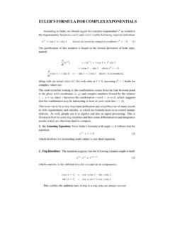
7 Consider a small element ofsuch atransmission lineof short elementary lengthz ,as shownin Figure1-1. The lower casezrepresents the distancemeasuredalong thelinewhich isalsothedirection of propagation. Figure1-1 representsthe section fromanunbalanced Transmission line , such as a coaxial cablewhich is themost common form oftransmission line . In unbalanced Transmission lines the return path comprises a metallicscreen surrounding the innercoaxial conductor used for the forward this case thereturn path will have low resistance and inductance, which is assumed negligibleandtherefore not shownin The fundamental elementsectionof a uniform TEM Transmission lineMany suchelementary sections may be cascaded toforma section ofa practical,uniformtransmission line .
8 The units of the elementary parameters are defined per unit lengthasfollows: 'R' Ohms per metre (/m ); 'L' Henries per metre (/H m); 'G' Siemens per metre (/S m); 'C' Farads per metre (/F m);The impedance of theseriessection represented byZ , with an upper caseZ, not to beconfused with the length which is a lower casezis:ZRj L ( ) Transmission Lines Page6 of 215 May 2011andthe admittance of the section is represented byY , whereYGj C ( )In( ) and( ) the term is the angular frequency of the applied sinusoidal waveformin radians per second (/rad s). is related to the frequency in hertz (Hz) of the waveformby:2f ( )By Kirchoff s lawsusing the definitions of voltages and current shown inFigure1-1:211 VVI Z z ( )212 IIV Y z ( )If the voltagedifference thereforeacrossz isV 211 VVVI Z z ( )1lim0VI ZzVVIZzzz ( )SimilarlyIYVz ( )Differentiating( ) with respect toz:2222()0 VIZZ YVYZVzzVYZVz ( )This differential equation expresses the voltage variation along the line in terms of , thefollowing differential equation may be derived in terms of the ( ) Total Voltage WaveA practicallineartransmission line will simply comprise a cascade of networksof the typeshown inFigure1-1.
9 It willhave some lossbecausefinite values forresistanceRandconductanceG. Eachof these parameterswill dissipate heat and therefore waste some ofthe powerintended forpropagation along thetransmission will also change withfrequency, the resistance and conductance tending to increase with increasing frequencybecauseofthe skin effect. Excessive heat dissipation is not usually a problem at lowpower levels but may become soat high power levelsif, forexample, the Transmission linewas usedto feed an antenna from ahigh powertransmitter. Inductance also changes withfrequency, tending to increase with increasing a Transmission line at high powers alsoincreases therisk of breakdownand/oroverheating. Breakdowncan occur very quickly, often being initiated by avery narrowpulse ofhigh instantaneous peak normallythe direct result ofTransmission Lines Page7 of 215 May 2011excessivemeanpowerbeing dissipated in theRandGel ements.
10 Either can causepermanent damageto thetransmission series element can be represented as an impedanceZ, given by:ZRj L ( )and the parallel element can be represented by an admittanceYgiven by:YGj C ( )( ) is a differential equation which has an exponential solution of the typezzVAeBe ( )whereAandBare constants and is the complex quantity given by ZYRj L Gj C ( )Furthermore is known as the propagation constant and is given byj ( )where is the attenuation constant expressed in Nepers per metre (/Np m) and is thephase constantexpressedin radians per metre (/rad m).A Neper is a logarithmic way of expressing a power ratio,with asimilardefinitionto thedecibel, butusing a natural logarithminstead ofa common logarithm.