Transcription of Triple Offset Butterfly Valves - Flowserve
1 FCD-DVENIM0400-00 Installation, Operation, and Maintenance Breaking the Barriers Flowserve TX2 Triple Offset Butterfly Valves Flow Control Division 2 TABLE OF CONTENTS section TITLE PAGE FOREWORD 2 I THEORY OF OPERATION 3 II PRELIMINARY PRECAUTIONS 3 III INSPECTION 4 IV TOOL REQUIREMENT 4 V STORAGE 5 VI INSTALLATION 5 VII STEPS OF INSTALLATION 5 VIII FLANGE CONNECTING AND BOLTING 7 IX REMOVAL PROCEDURE 8 X LUBRICATION SCHEDULE 8 XI STUFFING BOX MAINTENANCE PROCEDURE 8 XII CHANGE OF DISC AND BODY SEAT 11 XIII CHANGE OF GASKET 14 XIV ASSEMBLY AND DISASSEMBLY 14 XV PARTS AND SERVICE 16 XVI TROUBLESHOOTING GUIDE 17 XVII CAUTIONS 18 XVIII PARTS LIST AND MARKINGS 21 FOREWORD Flowserve Corporation, Flow Control Division, has established this Installation.
2 Operating and maintenance Manual to facilitate field installation, operation and repair of Flowserve TX2 Triple Offset Butterfly Valves It is recommended that questions or concerns involving the processes described in this manual be directed to the local Sales Representative of Flowserve Corporation. Only Flowserve replacement repair parts should be used. Part numbers referenced in the following sections are available from Flowserve Corporation, Flow Control Division. Flow Control Division 3 section I THEORY OF OPERATION The valve design is based on a double eccentric geometry of the disc rotating center, utilizing a floating radius machined seal ring, in conjunction with an inclined cone seating surface of body.
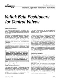
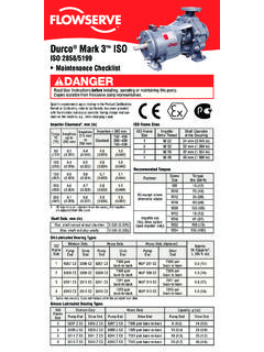
3 This design makes the disc cam back and away from body seat, eliminating wear between the seat and seal ring. It also compensates for deviations of the geometry caused by temperature or tolerance changes. (Fig. 1) The disc seal of valve deflects from its regularly circular shape to an elliptic form when it reaches the closed position. This matches the inclined cone of body seat geometry, creating the sealing between disc seal and body seat. Dimension changes due to temperature fluctuations cause the seal ring to adjust its seating position within the inclined cone geometry, thus maintaining a positive seal as usual. Due to the unique conical surface of the valve, there is a preferred and non-preferred flow direction.
4 The preferred flow direction would be with the shaft upstream and the direction is marked on the body with a directional arrow. The shaft side is referred to as the high pressure side of the valve. section II PRELIMINARY PRECAUTIONS FOR SAFETY, FOLLOW THESE CAUTIONS BEFORE INSTALLING, REMOVING OR DISASSEMBLING YOUR VALVE. 1. MUST KNOW WHAT MEDIA IS IN THE PIPELINE. 2. MAKE SURE THE LINE IS DEPRESSURIZED. 3. USE PROTECTIVE CLOTHING AND EQUIPMENT TO AVOID INJURY. KEEP HANDS AND OTHER BODY PARTS OUT OF THE VALVE. 4. ALWAYS ENSURE THE VALVE IS IN THE FULLY CLOSED POSITION BEFORE INSTALLATION, REMOVAL OR DISASSEMBLY. 5. ENSURE THAT FLANGE FACES ARE CLEAN BEFORE INSTALLATION IN PIPELINE. Preferred direction of flow Flow Control Division 4 section III INSPECTION 1.
5 Before installation of the valve into the piping system, visually inspect the valve to determine if any damage has occurred during shipping. Particularly, inspect the actuator, shaft, valve interior, valve body and flanges. For proper operation of the Valves , the seat and disc seal must be undamaged and free of foreign material. If other than superficial damage is discovered, contact Flowserve immediately, indicating the location and extent of the damage found. 2. If it is necessary to clean the valve, use a soft cloth and mineral spirits, or an equivalent solvent. All rust preventive should be removed before installing your valve. section IV TOOL REQUIREMENT There are no special tools required for installation and maintenance that are not commercially available.
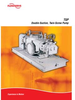
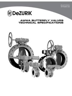
6 Any lifting devices used to move the valve into a desired position shall be of sufficient size to support the weight of the valve and actuator assembly. Nylon slings secured around the valve bearing areas are recommended to reduce the possibility of mechanical damage occurring to the valve body and actuator. The assembly should never be lifted by the actuator. ( ) WARNING NEVER pass a lifting device through the valve port or severe damage may occur. Fig. 2 Flow Control Division 5 section V STORAGE When the valve is not put into immediate service, it is required that the valve be stored in a heated building that is fire resistant, weather tight and well ventilated. Storage area shall be situated and constructed so that it will not be subject to flooding or the presence of any corrosive chemicals.
7 Flowserve recommends that all valve actuators be cycled approximately every 60 days or as required by the manufacturer of the actuation system. Any spare parts for the valve shall be stored in the original packaging and under the same conditions as the valve will be stored. For storage greater than 4 months, the storage container should be inspected every four (4) months to ensure it is in good condition, and any additional protective coverings or materials are in working order. Ensure all parts are plugged, and bare metal is covered with a suitable rust inhibitor. section VI INSTALLATION The valve must be installed so that pipeline stresses are not transmitted to the valve body. Despite its solid manufacture, such stress may affect valve operation.
8 If pipeline stresses are severe, they should be cushioned by expansion joints or compensators. If supports are necessary for the valve, they should only support the dead weight of the valve and should not serve as base points for the pipeline. section VII STEPS OF INSTALLATION All valve s must be in full closed position during installation or removal. It is not necessary to torque seat the valve, but the disc travel must be restricted to prevent damage. Please be sure there is no foreign material and that it is clean inside of the pipe and valve. The shaft side of the disc is considered the high-pressure side of the valve, (as indicated on the drawings by a flow arrow) meaning the best closure performance is obtained on this side of the valve, and a determination as to the best installation should be made, to utilize this feature.
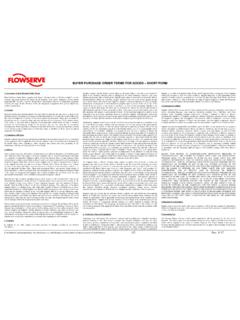
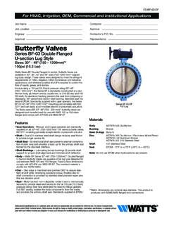
9 This may not necessarily be the normal flow direction of the system. ( ). Please install the valve stem horizontally as ( ), thus could prevent sand and some chips from collecting around bottom bushing and seat. Such reside could damage the valve. Fog 4 Fig 4 Fig 3 Fig 4 Flow Control Division 6 Install valve and gaskets into pipeline as ( ). Fig 5 Make sure that the valve is installed concentrically between the flanges in order to could prevent the disc from being damaged by interference with the flange and pipeline ( ) The typical installation for a Butterfly valve connected to an elbow would be to align the shaft axis to allow equal flow on each side of the shaft, minimizing dynamic torque requirements for the valve.
10 ( ) Excellent Good Not recommended Fig 7 Always use an extension tube between wafer check valve and Butterfly valve. Never connect them directly. ( ) Fig 8 Fig 6 Flow Control Division 7 section VIII FLANGE CONNECTING & BOLTING Keep valve protection boards until installation. Make sure the material and size of gaskets could be suitable for the service. Ensure that the faces of flange and valve are smooth and flat. Sandpaper the faces if there are any defects. Check that all the bolts and nuts are in good condition. Apply lubricant such as Molybdenum to all the bolts and nuts before fixing them.