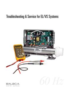
Transcription of Troubleshooting & Service for EL/VS Systems
1 1 Troubleshooting & Service for EL/VS Systems60 Hz2 Balboa s Patented M7 TechnologyTOPSIDE CONTROL PANELThe control panel activates functions at the touch of a button. Each function will echo from the circuit board to the LCD in a corresponding manner. The panel will also display diag-nostic messages that enable the Service technician to easily troubleshoot the TECHNOLOGYM7 is a patented Balboa technology that uses two sensors inserted at the opposite ends of the heater element to determine flow, dry fire conditions, etc. The two sensors located within the heater housing compare the inlet water temperature with the outlet water temperature. It works no matter which direction the water flows through the heater. The sensors in combination with specific software allow the spa to be controlled without the use of external pressure switches, flow switches, or temperature Top Side PanelPanel ConstructionVS501 with a Cut-a-way View of the HeaterSensorSensor3 Table of ContentsBalboa s Patented M7 Technology.
2 2 Balboa Service Tools and Parts Checklist .. 5 Important Information -- Product Identification ..6 Troubleshooting & Servicing Spa and Electrical Equipment .. Troubleshooting .. 8If Correct Wiring is Verified .. 8To Disconnect the Heater .. 8 Voltage Checks: Breaker Box, & System Box .. 9 Wiring Checks .. 14 Spa Behavior -- Start-up Information .. 15 Priming Mode .. 15 Heater Start up Information .. 15 Diagnosing M7 Topside Control Panels .. 16 Checking the System Power Input Fuse .. 19ML Series Panels -- For Use with EL and GL Systems .. 21ML900 Panel Operation .. 22ML700 Panel Operation .. 23ML550, 551, 554 Panel Operation .. 24ML200, 240, 260, 400 Panel Operation .. 28VL Series Panels -- For use with VS and GS Systems .
3 32VS/GS Panel -- 300 & 500 Series and Operation .. 34EL and GL Series Mach 3 -- Persistent Memory & Power Up .. 38EL - GL, about Persistent Memory .. 38 Power Up Display Sequence, Software ID .. 38VS-GS Persistent Memory with VL Panels .. 39 Testing the Circuit Board Output .. 40 Balboa s Quick TestTM Test Kit .. 40To Use the Balboa Quick Check .. 40 Testing the Sensor Set .. 41 Changing a System Circuit Board .. 42 How to Remove a System Circuit Board .. 42 How to Replace a System Circuit Board .. 42 Removing the Heater Assembly from a Spa System .. 43 Panel Message Reference Guide .. 444300/300F/500Z Series Panel ..34500DZ Series Panel ..34500SZ Series Panel ..34 Balboa QuickCheckTM part No. 70002 .. 40 Ground-Fault Circuit Interrupter/Circuit Breaker ( ).
4 8120 Volt Residential Wiring Schematic with .. 10240 Volt Residential Wiring Schematic with .. 12 Ground in System Enclosure .. 7 Heater Element Specifications Are Shown on the Heater Tube Label .. 6ML260, ML240, ML200 .. 28ML400 .. 28ML550 .. 24ML551 .. 24ML554 .. 24ML700 Top Side Panel .. 2 Recommended Parts For Service Calls .. 5 Service Tools Required .. 5 Molex Type, ML/GL Connector .. 6On Every System, an Identification Label Is Placed on top of the Casing .. 6On Every System, a Wiring Diagram Is Placed Inside the Door .. 6 Panel Construction .. 2 Phone Plug RJ Type, VL/GS Connector .. 6 Phone Plug RJ Type, VL/VS Connector .. 32 Terminal Block 1 & F5 Fuse on a VS500Z Board.
5 19VS500 Board ..42VS501 with a Cut-a-way View of the Heater .. 2 Diagrams (in alphabetical order)5 Balboa Service Tools and Parts ChecklistService Tools RequiredAmmeter (50A)U Balboa Six-in-one ScrewdriverU Digital Multi-meterU Padlock (to lock electrical disconnect during Service )U Pliers: Slip Joint & Needle noseU Recommended Parts For Service CallsExtra Board(s)U Extra Panel(s)U FusesU JumpersU Heater AssemblyU 20618 JUMPER LOGICCOMMON FUSES USED30074 FUSE 1 AMP FAST BLOW GLASS30075 FUSE 5 AMP FAST BLOW GLASS30122 FUSE 10A BLOWER30595 FUSE 10A POWER INPUT30076 FUSE 15 AMP FAST BLOW CERAMIC30596 FUSE 15A POWER INPUT30142 FUSE 20A POWER INPUT30123 FUSE 20A PUMP30137 FUSE 25A POWER INPUT21447 FUSE 25A POWER INPUT HIGH SURGE30136 FUSE 30A POWER INPUTMORE COMMON BOARDS.
6 22972 BOARD BARE VS500 (shown)21998 BOARD BARE GL200027116 BOARD BARE EL500053649 ML700 Heater AssemblyPrecision Thermometer - Digital Fever TypeU Quick CheckTM Test KitU Silicone TubeU Small Wire CuttersU Two 3/8 Open End Wrenches (one wrench should be U ground down to 5/32 [ ] thickness in order to access the nut between the heater strap and heater element connector)6On Every System, an Identification Label Is Placed on top of the CasingHeater Element Specifications Are Shown on the Heater Tube Label On Every System, a Wiring Diagram Is Placed Inside the Door Important Information -- Product IdentificationTwo Types of Plug-in Connectors: Molex Type, ML/GL Connector Phone Plug RJ Type, VL/GS Connector 7 Troubleshooting & Servicing Spa and Electrical Equipment DANGER Risk of electric shock.
7 Before working with any electrical connections, make certain that the Main Power breaker from the house breaker box has been turned off. WARNING All electrical work must be performed by a qualified electrician and must conform to all local codes. IMPORTANT Due to the danger of severe electrical shock, locate all power disconnects before servicing a spa. Precautions must be taken whenever working with breaker boxes, s, or Service refer to the wiring diagram which is included U with each system on the inside of the system box cover. Use this diagram for voltage measurement points, and for proper reconnection of VOLTAGE CAN SERIOUSLY INJURE OR KILL!ONLY EXPERIENCED TECHNICIANS SHOULD Service THIS NOT remove the protective covers from any electrical enclosure, or attempt to Service any related electrical device, unless you are a qualified electrician or Service professional.
8 Safety TipsKeep children and pets Be aware of your surroundings. Standing in water while U repairing a spa puts you at serious working in cramped or crowded Consider placing a padlock on the Service panel to lock U out anyone who might power up the system. A terminal marked GROUND is provided within the System Control Center enclosure. To reduce the risk of electrical shock, connect this terminal to the grounding terminal of the electric supply panel with a continuous green insulated copper wire equivalent in size to the circuit conductors supplying this equipment, but no smaller than #12 AWG. Ground in System TroubleshootingIF CORRECT WIRING IS VERIFIEDC heck to see if the proper is Check the label in the system box near TB1 to determine U the maximum amperage draw for the sure the is rated for more amperage than the U system will a 240 V dedicated system, a 2-pole with no U load neutral is a 120/240 V system, the must include a load U neutral the white load neutral wire is routed from the U neutral bar directly to TB1 in the system box, then the will trip when a 120 V device is a detailed wiring checklist, please review the U previous segment of this manual on proper wiring or the manufacturer s the wiring is correct and the will not reset, then U unplug the pump and try to reset the the trips again.
9 Then unplug the blower and U reset the If the continues to trip, then do the same procedure for the ozone the stops tripping after you unplugged one of U the spa s components, turn off the power to the spa then plug in each component except the one that tripped the up the system. If the no longer trips, U then you have correctly identified the problem. Repair or replace the component as instructed by the spa you have unplugged all of the spa s components and U the still doesn t reset, then the problem is most likely a ground fault in the DISCONNECT THE HEATERF irst, turn off the main circuit breaker, then remove both U heater straps or wires from the system heater output, not the heater restoring the power, try to reset the again. U If it no longer trips after the system calls for heat, then replace the the still trips, look for pinched or shorted U wires at the transformer.
10 Make sure that the screws that attach the transformer to the system box have not pinched or damaged the insulation of the transformer the transformer wires are undamaged, check for any U other pinched wires. Refer to the wiring diagram to verify the correct wiring of the control everything looks to be in perfect working order, then U the may be in mind that a majority of tripping problems can be attributed to incorrect wiring. Troubleshooting usually finds the Circuit Interrupter/Circuit Breaker ( )WARNING: THE OWNER SHOULD TEST AND RESET THE ON A REGULAR BASIS TO VERIFY ITS Verification - Most Problems Are Due To Low Voltage IMPORTANT: IF THE VOLTAGE IS NOT WITHIN THE ACCEPTABLE RANGE, CALL AN ELECTRICIAN OR THE LOCAL ELECTRIC COMPANY TO DIAGNOSE THE THE VOLTAGES AT: 1.
