Transcription of Troubleshooting Radios - W8KVK
1 From May 2009 QST ARRL pensive signal generator should be used to inject enough power to obtain an S-9 + 10 dB signal. Remember your radio must be on USB with the generator s frequency 1 kHz above the radio s frequency to receive the audio tone. The actual audio frequency is not important long as you get a good iden-tifiable at your OutputHook up a shielded lead from the AUDIO OUT jack of the radio to one VERTICAL INPUT connector of the scope. On the 102, I use the AUDIO OUT jack of the six socket RCA connector board on the back of the set.
2 In any other radio , just connect a wire to any audio source including the speaker leads and hook that up to the INPUT connector of your scope. Adjust the scope VERTICAL GAIN control or the radio s AF GAIN control until the signal fills six large vertical divi-sions centered in the cathode ray tube (CRT) display. Adjust the TIME BASE control for 5 , turn the automatic gain control (AGC) circuit to OFF. This switch is on the front panel of the 102 but other Radios may vary. Be careful, as the audio may become very loud and distorted and the signal will be off the scope.
3 Adjust the RF gain control so that the signal level on the CRT screen is at the same level as before pushing the AGC to the OFF position. This will decrease the audio output and its distortion to the previ-ous normal level. Follow the same proce-dure with any other this point any sig-nal path loss no mat-ter how slight will be reflected by a change in the signal s amplitude on the CRT. You will be able to see a dB change in level. This is because the AGC is defeated and you are not in saturation of the result-ing IF or audio signals. A 6 dB power loss anywhere from the antenna input to the final audio amplifier, will halve the voltage ampli-tude of the CRT trace.
4 This will be reflected by I have been repairing the Yaesu FT-102 HF transceiver for the past 19 years and have spent more than 10,000 hours in this endeavor on this one radio model alone. In all, I have worked through problems in sev-eral hundred of these Radios over the period. As you may be aware the most significant problem with this radio (as well as many others) is intermittent signal path losses. I am trained as a cardiologist and never had any formal training in Troubleshooting RF circuitry, except in my pursuit of perfection for the 102.
5 During this time I have accu-mulated a wealth of knowledge in how to track down these problems in the 102, as well as in most other Radios and I would like to share these principles with s like the old proverb that if you give a man a fish you feed him for a day but if you teach him how to fish you will feed him for the rest of his life. The principles that I am going to share with you are easy to understand and perform by almost any ham. Finding an intermittent and then sledgeham-mering it into the ground (I am not speaking literally, of course) so that it never, never occurs again is a true joy and an enormous source of satisfaction.
6 Although my exam-ples are for the 102 they can be applied to other ham radio equipment . Let s Get Started Here s What You NeedThere are three instruments that you must have. The first is the digital mul-timeter that most hams already possess. The second is an oscilloscope noth-ing fancy is required, since it will be mostly used at audio frequencies. It must, however, be an analog type. Digital scopes will not always give you the instantaneous infor-mation you need because they are not real time instruments. Good scopes can be obtained at ham-fests or on the internet for $50 to $100.
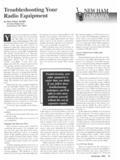
7 They are all-powerful when used for Troubleshooting (see Figure 1). The third instru-ment is your own intuitive brain. It is the most important of all the Troubleshooting instruments. One other possibility is a low tech sig- Troubleshooting RadiosBefore you pack it up and ship it off, check it out Eiselman, NC4 Lnal generator (nothing fancy is needed) and this is required only if your radio does not have a marker or calibrator function. Here is how I troubleshoot a 102. The First Step Get a Signal to Work WithTurn on the transceiver and set the fre-quency to 14, kHz, the mode to USB and the RF amplifier to ON.
8 If you can disable the transmitter, do so or be careful not to switch to TRANSMIT during this test. Leave the antenna unconnected. Keep the SHIFT and WIDTH controls centered, straight up on the 102. Turn on the 25 kHz marker signal (at the back chassis on the 102) or set your signal generator to 14, kHz. If your calibration is close, you should receive a tone of about 1 kHz (14, 14, kHz). Peak the preselector for maxi-mum signal on the S-meter. These maneuvers will provide you with a strong IF signal and 1 kHz audio tone from your speaker because of the USB offset.
9 Adjust the VOLUME control for minimal audible signal as the sound is not important in this part of the test. If the relays and the rest of the receiver are working properly at that moment you should read a signal of +10 to +15 dB over S-9 on a 102 and something similar on other transceivers. If you do not have a calibrator in your radio , then an inex-Figure 1 An oscilloscope that is typical of those that can be pur-chased from eBay or at hamfests for $50 to $100. It is a dual channel scope with 35 MHz bandwidth more than is usually May 2009 QST ARRL your audio signal s vertical amplitude dropping from six divisions of the scope (total excursion) to three divisions.
10 What s it all Mean?This degree of RF or IF signal loss would not be heard with usual on- the-air circumstances with the AGC engaged. That is because the AGC s function is to compensate so that the audio voltage and volume stay the same even though the input varies. You would not notice a 6 dB difference on an on-air signal with fad-ing (QSB) and static. It is too small a change unless the signal is very near the noise level. Remember, however, that in reality a 6 dB loss represents losing 75% of the power of your received signal. On the other hand when people lose their S meter deflection or their receiver drops out they are having a 60 to 100 dB loss of signal.