Transcription of TrueAlert Multi-Candela Notification Appliances
1 Features Audible/visible (A/V) Notification Appliances with efficient electronic horn and high output xenon strobe, available for wall or ceiling mount Operation is compatible with ADA requirements (refer to important installation information on page 3) Rugged, high impact, flame retardant thermoplastic housings are available in red or white with clear lens Operates over a two-wire SmartSync circuit to provide: Horns that are controlled separately from strobes on the same two-wire circuit On-until-silenced and on-until-reset operation on the same two-wire pair SmartSync horn activation of Temporal pattern, March Time pattern (at 60 BPM), or on continuously Strobe Appliances on the same circuit operating at a synchronized 1 Hz flash rate Class B operation requires connection to a compatible SmartSync NAC or to SmartSync Control Module (SCM) 4905-9938 Class A operation when connected to the 4905-9938 SCM or with 4100U series fire alarm control panel NACs Wall mount A/Vs features.
2 Wiring terminals are accessible from the front of the housing providing easy access for installation, inspection, and testing Covers are available separately to convert housing color Available UL listed sound damper for locations requiring attenuation of 5 to 6 dBA (stairwells, small rooms, highly reverberant areas, etc.) Optional adapters and wire guards: Wall mount A/V adapters are available to cover surface mounted electrical boxes and to adapt to Simplex 2975-9145 boxes UL listed red wire guards are available for wall or ceiling mount A/Vs Visible Notification appliance (strobe): 24 VDC xenon strobe; intensity is selectable as 15, 30, 75, or 110 candela with visible selection jumper secured behind strobe housing UL listed to Standard 1971 Regulated circuit design ensures consistent flash output and provides controlled inrush current Audible Notification appliance (horn): Low current, 24 VDC electronic horn with harmonically rich sound output suitable for either steady or coded operation (Temporal or 60 BPM March Time pattern) UL listed to Standard 464 Wall and Ceiling Mount A/Vs Description Multi-Candela TrueAlert A/Vs with horn and synchronized strobe provide convenient installation to standard electrical boxes .
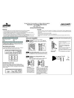
3 The enclosure designs are both impact and vandal resistant and provide a convenient strobe intensity selection. Since each model can be selected for strobe intensity output, on-site model inventory is minimized and changes encountered during construction can be easily accommodated. Wall mount A/V housings are a one-piece assembly (including lens) that mounts to a single or double gang , or 4 square standard electrical box. The cover can be quickly removed (a tool is required) and covers are available separately for color conversion. Ceiling mount A/Vs install using standard 4 electrical boxes . Color choice is determined by model number. Strobe Intensity Selection During installation, a selection plug at the back of the housing determines the desired strobe intensity. An attached flag with black letters on a highly visible yellow background allows the selected intensity to be seen at the side of the strobe lens.
4 * This product has been approved by the California State Fire Marshal (CSFM) pursuant to Section of the California Health and Safety Code. See CSFM Listing 7125-0026:317 for allowable values and/or conditions concerning material presented in this document. Accepted for use City of New York Department of Buildings MEA35-93E. Refer to page 2 for listing status of wire guards. Additional listings may be applicable; contact your local Simplex product supplier for the latest status. Listings and approvals under Simplex Time Recorder Co. are the property of Tyco Fire Protection Products. TrueAlert Multi-Candela Notification Appliances UL, ULC, CSFM Listed; FM Approved; SmartSync Operation Audible/Visible Notification MEA (NYC) Acceptance* with Horn and Synchronized Flash, Non-Addressable S4906-0002-6 11/2014 Strobe Application Selection Proper selection of visible Notification is dependent on occupancy, location, local codes, and proper applications of: the National Fire Alarm Code (NFPA 72), ANSI ; the appropriate model building code: BOCA, ICBO, or SBCCI; and the application guidelines of the Americans with Disabilities Act (ADA).
5 Synchronized Strobes Multiple Strobes. When multiple strobes and their reflections can be seen from one location, synchronized flashes reduce the probability of photo-sensitive reactions as well as the annoyance and possible distraction of random flashing. The Multi-Candela strobes of these A/Vs are synchronized by the controlling SmartSync operation NAC. SmartSync Two-Wire Control SmartSync operation mode allows a two-wire circuit to provide the ability to activate both the horn and strobe on the same NAC and then allow the horn to be silenced while the strobe remains flashing. The horn operates as on-until-silenced while the strobe operation is on-until-reset. SmartSync Control Sources 4006, 4007ES Hybrid, 4008, 4010, 4010ES, 4100ES, and 4100U Fire Alarm Control Panels (refer to individual product data sheets for more information) 4009 IDNet NAC Extender (refer to data sheet S4009-0002) SmartSync Control Module (SCM) 4905-9938 (refer to data sheet S4905-0003) Additional SmartSync compatible Notification Appliances include separate horns and combination horn/strobe Notification Appliances .
6 2 S4906-0002-6 11/2014 Multi-Candela A/Vs Model Mounting Housing Color FIRE Lettering Description 4906-9127 Wall Red White Horn with Multi-Candela Strobe; strobe intensity selectable as: 15, 30, 75, or 110 candela; operates with SmartSync two-wire control 4906-9129 White Red 4906-9128 Ceiling Red White 4906-9130 White Red Wall Mount A/V Accessories Model Description Dimensions 4905-9937 Red Surface Mount Adapter Skirt; use to cover 1-1/2 (38 mm) deep surface mounted boxes 5-3/8 H x 5-1/4 W x 1-5/8 D (136 mm x 133 mm x 41 mm) depth with strobe = 4-3/8 (111 mm) 4905-9940 White 4905-9931 Red Adapter Plate for mounting to Simplex 2975-9145 box (typically for retrofit, may be mounted vertical or horizontal) 8-5/16 x 5-3/4 x Thick (211 mm x 146 mm x mm) 2975-9145 Red Mounting Box, requires Adapter Plate 4905-9931 7-7/8" x 5-1/8" x 2-3/4" D (200 mm x 130 mm x 70 mm) 4905-9838 Optional Sound Damper; package of 20; field installed adhesive backed horn output attenuator.
7 Reduces output 5 to 6 dBA NOTE: After Sound Damper installation, measure sound level to ensure compliance with applicable code requirements 1-3/4 Diameter ( mm) with (8 mm) sound opening SmartSync Control Module Model Description Dimensions 4905-9938 SmartSync Control Module with Class B or Class A output; mounts in 4 (102 mm) square box; refer to data sheet S4905-0003 for details 4 x 4-1/8 x 1-1/4 D (102 mm x 105 mm x 32 mm) Replacement Covers for Wall Mount A/Vs Model Description Dimensions 4905-9994 Red cover with white FIRE lettering 5-1/8 H x 5 W x 1-1/2 D (130 mm x 127 mm x 38 mm) 4905-9995 White cover with red FIRE lettering Wire Guards and Ceiling Mount A/V Adapter Model Description Dimensions 4905-9961* Wall mount red wire guard with mounting plate, compatible with semi-flush or surface mounted boxes 6-1/16 H x 6-1/16 W x 3-1/8 D (154 mm x 154 mm x 79 mm) 4905-9927* Ceiling Mount Red Wire Guard for mounting to flush mounted electrical box 8-1/2 x 6-1/8 x 3 (216 mm x 156 mm x 76 mm) 4905-9928* Red Adapter Plate, required to mount guard to surface mounted electrical box 9 x 7 (229 mm x 178 mm)
8 4905-9915 White Surface Mount Adapter Box Extension, use to cover 1-1/2 deep surface mounted boxes 4-3/4" x 6-7/8" x 1-1/2" deep, (121 mm x 175 mm x 38 mm) 4905-9916 Red * UL listed by Space Age Electronics Inc. Product Selection 3 S4906-0002-6 11/2014 Wall Mount or Ceiling Mount, Common Specifications Rated Voltage Range UL Listed Rating Regulated 24 DC; see Note 1 below ULC Listed Rating 20 VDC to 30 VDC per ULC S526-M878 Flash Rate and Synchronized NAC Loading 1 Hz; with up to 35 synchronized strobes maximum per NAC Environmental; Temperature and Humidity 32 to 122 F (0 to 50 C); 10% to 93%, non-condensing at 100 F (38 C) Connections Terminal blocks for 18 AWG to 12 AWG ( mm2 to mm2); two wires per terminal for in/out wiring Horn Output Characteristics 2400 to 3700 Hz sweep, modulated at 120 Hz rate Horn Output Ratings @ 10 ft (3 m) (see Note 2) Voltage 16 VDC 24 VDC 33 VDC Sound Type (see Note 2) Steady Coded Steady Coded Steady Coded UL 464 Reverberant Chamber 86 dBA 82 dBA 88 dBA 84 dBA 90 dBA 86 dBA Anechoic Chamber 92 dBA 91 dBA 94 dBA 95 dBA 96 dBA 96 dBA Wall Mount Housing Dimensions (with lens) 5-1/8 H x 5 W x 2-3/4 D (130 mm x 127 mm x 70 mm) Maximum RMS Current Rating per Strobe Setting (see Note 3 below) 15 cd 30 cd 75 cd 110 cd 75 mA 116 mA 221 mA 285 mA Reference RMS Currents at other voltages 18 VDC 67 mA 103 mA 196 mA 253 mA 24 VDC 50 mA 77 mA 147 mA 190 mA Ceiling Mount Housing Dimensions (with lens)
9 4-3/4 L x 6-7/8 W x 2-5/8 D (121 mm x 175 mm x 67 mm) Maximum RMS Current Rating per Strobe Setting (see Note 3 below) 15 cd 30 cd 75 cd 110 cd 86 mA 132 mA 250 mA 320 mA Reference RMS Currents at other voltages 18 VDC 76 mA 117 mA 222 mA 284 mA 24 VDC 57 mA 88 mA 167 mA 213 mA NOTES: 1. Regulated 24 DC refers to the voltage range of 16 to 33 VDC per UL Standard 1971, Signaling devices for the Hearing Impaired. This voltage range is the absolute operating range. Operation outside of this range may cause permanent damage to the appliance. Please note that 16 VDC is the lowest operating voltage that is allowed at the last appliance on the NAC under worst case conditions. 2. Coded values are typical of the output measured with a Temporal coded or a March Time coded pulse and with a sound level meter reading on a fast setting. Under the same test conditions, coded horn output peak sound level readings are typically 4 dBA higher.
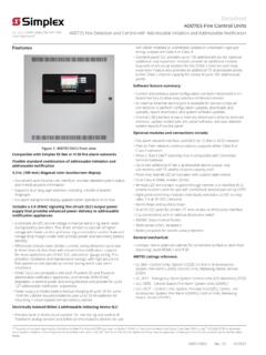
10 Anechoic horn output ratings are typically more representative of actual installed sound output. 3. Currents are with horn on steady. The maximum RMS current listed is the device nameplate rating. Strobe designs are constant wattage and the maximum RMS current rating occurs at the lowest allowable operating voltage. (RMS is root mean square and refers to the effective value of a varying current waveform.) Removable cover(tool required)Mounting is compatible withsingle gang , double gang , and4" (102 mm) square boxes ,1-1/2" (38 mm) deep, by others2134 Mounting Holes:4" square (4)Single gang (2)Double gang (3)Wiring access holeWiring terminals forSmartSync operationTransparent housingand lens assemblyStrobe intensityviewing slotIntensity selectionplug, accessible onlyfrom rear of housing;factory setting is 15 cd110753015 Optional 4905-9838 Sound Damper, field attachedto attenuate sound 5 to 6 dBA aNFPA 72 requiresthat the entire lensbe not less than80" and not greaterthan 96" above thefinished floorElectricalbox outline80" ( m)minimumBottom of lensis either evenwith, or slightlyabove bottomof compatibleboxesIMPORTANT!