Transcription of TSRH Pedicle Screw ST - MT Ortho
1 tsrh Pedicle Screw Spinal SystemSurgical Techniqueas described by:Edward H. Simmons, D. Simmons, Jr., Orthopaedic AssociatesState University of New York atBuffalo, Buffalo, New YorkDegenerative SpondylolisthesisSURGICAL TECHNIQUETSRH StepsRadiological 1 0 surgical Technique StepsIdentification of The Pedicles .. 1 1 Preparation of The Pedicle 1 2 Tapping The 1 3 Determining Screw Length/ Screw 1 4 tsrh Variable Angle Screw 1 5 Developing The Fusion 1 6 Construct Assembly:Spondylolisthesis at 1 7 Rod Selection, Cutting, 1 8 Construct 1 9 Low Profile CROSSLINK Plate 24 Postoperative Care and 26 surgical TECHNIQUETSRH PREFACE2 Dear Fellow Surgeon:Historically, severe disability from major deformity of degenerative spondylolisthesis has presented a major challenge for the surgeon and difficult courses of treatment for the patient.
2 The aims have been to obtainsolid arthrodesis and where possible to effect reduction to at least improvethe slip angle , so that the mobile spine above has a more normal angle ofsupport in relation to the horizontal. Attempts at closed reduction havebeen difficult, relatively unsuccessful and disabling. Prolonged immobilizationhas been up to 3 months on a Stryker frame or in a plaster bed to allowsuccessful maturation of the fusion mass. In an effort to allow some degreeof mobilization while fusion occurred, plaster body casts of the hip spicatype were used and finally braces including the thigh. Despite the magnitudeof these treatments for the patient, there was still an unfortunately high rateof use of internal fixation with Pedicle screws has provided an excellentinternal splint to stabilize the spine, dramatically improving the fusion rateand at the same time offering a reasonable degree of effective reductionwith improvement of the slip angle.
3 The tsrh Pedicle Screw Spinal System provides the opportunity of effec-tively immobilizing the spine along with a reasonable degree of correctionand at the same time allowing the most important part of the operation tobe carried out, namely a very effective, meticulous spinal fusion with ampleautogenous tsrh Pedicle Screw Spinal System allows the application of bone graftto the spine. It allows easy contouring of the fixation system to improve andmaintain the patient s spinal alignment. tsrh Variable Angle T-bolts now allow easier insertion of the rods if thepedicle screws are not in perfect alignment, decreasing operative timeand increasing the ease of the system allows fulfillment of the aims of the operative procedure, namelyto provide effective immobilization of the involved segments while fusionoccurs and to provide reasonable reduction where ,Edward H.
4 Simmons, MDEdward D. Simmons, Jr. MDSURGICAL TECHNIQUETSRH 3 IMPLANTSTSRH Pedicle Screw SPINAL SYSTEM IMPLANTSTSRH CROSSLINK SYSTEM IMPLANTSLOW PROFILE CROSSLINK SYSTEM IMPLANTSVa r iableAngle ScrewVariable Angle T-BoltSmallDouble HexLocking ScrewStandard BreakLock ScrewVariable Angle T-BoltMediumAvailable in Stainless Steel or Titanium, (14") RodDiametersRodActual Length: 20"PlateLocknutCROSSLINK PlateCROSSLINKM ulti-Span PlateCROSSLINK OffsetPlateEyeboltWARNING:Do not intermix Stainless Steel with TitaniumVariable Angle T-BoltLargeFlush BreakLock ScrewSURGICAL TECHNIQUETSRH 4 tsrh Pedicle Screw SPINAL SYSTEM INSTRUMENTSP edicle ProbeQC Awl ShaftScrew GaugeQC Ratcheting HandleDual Screw Driver ShaftStraight Holt ProbeRound Holt ProbeRod TemplateT-Bolt PositionerFrenchRod BenderOffset Mini-CorkscrewPositioning ClipCentral Post Hook HolderFixed QC Egg HandleQCCannulated TapINSTRUMENTSSURGICAL TECHNIQUETSRH 5 LOW PROFILE CROSSLINK SPINAL SYSTEM INSTRUMENTSNOTE.
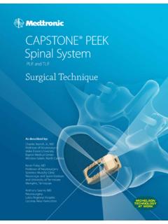
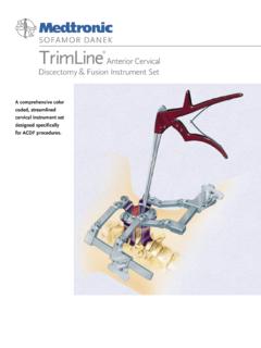
5 For a complete listing of sizes and catalog numbers for the tsrh Pedicle Screw Spinal System implants and instruments, please refer to the Medtronic Sofamor Danek Product mplateHex HeadScrewdriverPlateBendersPlateHolderTS RH Pedicle Screw SPINAL SYSTEM INSTRUMENTSC ounter Torque Wrench7/32 Socket Drive ShaftRadiological StudyPRELIMINARYSTEP 16 Comprehensive radiological studies, including plain radiographs (A/Pand lateral standing), CT and MRI scans, are essential to determinethe existence and extent of neural compression subsequent tosevere cases of spondylolisthesis (grades 3 & 4) at L5-S1. In addition flexion and extension lateral radiographs can indicate the degree of mobility of the listhesis, indicating the least amount of reduction that may be readily obtained and maintained with scan or MRI scan evaluations have proven to be a very effectivediagnostic and preoperative planning Standing RadiographA/P RadiographRadiological StudySTEP 17 PRELIMINARYP ostoperative Lateral RadiographPostoperative A/P RadiographCT Scan: Area of SpondylolysisMRI: Lateral Recess Stenosis8 Preoperative PlanningThe necessary lordotic alignment can be determined through careful review and analysis of the lateral standing plain film.
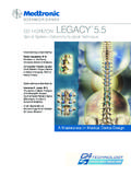
6 The appropriate tsrh Variable Angle Pedicle Screw can also be determined at this scans (axial images) can be used preoperatively to measure the diameter of the pedicles and select the appropriate length anddiameter of the Pedicle screws to be implanted (Fig. 1). The widthof the Pedicle is measured at its isthmus. Two measurements aretaken: (a) medial cortical wall to lateral cortical wall, and (b) medialto lateral endosteal cortical medial angle of the pedicles should also be assessed as a guideto Screw appropriate Screw diameter is one that completely fills theendosteal cortical canal of the Pedicle . The Screw length shouldextend 50-80% into the vertebral body. For L5, the most commonTSRH Pedicle Screw used is a diameter by 45mm :Remember to account for the Xray, CT or MRI magnification factor when taking these 2 AABBFig.
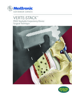
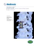
7 19 Patient Positioning/AnesthesiaThe patient is positioned on the operating table in theprone position (Fig. 2). A spine surgery frame should beused which will avoid any pressure on the abdomen,thereby avoiding vena caval compression. Hypotensiveanesthesia, autotransfusion and a cell-saver may also beused to reduce intraoperative blood loss. Radiographicguidance and control, either fluoroscopic with imageintensifier or quality Xrays are used intraoperatively. Prior to skin prep and draping, the patient s position may be checked radiographically (C-arm or Xray) to determine the axial direction of the pedicles to the 3 Fig. 210 surgical ApproachThe surgical approach is carried out through a standard midline incision to the spinal column over the anatomic position of the spinous processes. The incision should be long enough to ensureexposure of L3 through S1.
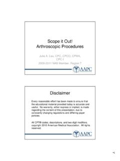
8 Initially, the positions of the spinousprocesses are identified through palpation and the lumbar facia isincised on the sides of each of the spinous process. The supraspinousand interspinous ligaments should be preserved particularly abovethe area of instrumentation, as these are important posterior sub-periosteal exposure of the posterior elementsis performed. The paraspinal musculature is detached to the outer margins of the transverse processes. When indicated, soft tissue and bony decompression is performed to relieve neurological compression. The capsule and articular cartilage of the facet joints to be included in the fusion are excised. When necessary, decompressive laminectomies are performed to correctany stenosis in the central canal along with lateral recess and neuralforaminal can now be carried out as 4 surgical TECHNIQUE11 Identification of the PediclesThe entrance to the intramedullary canal of the Pedicle is located at the point where the middle of the transverse process, superior facet and pars interarticularis converge ( ).
9 The entrance to the S1 Pedicle is caudal and just slightly lateral to the superior articular process. The Pedicle canals of L4, L5 and S1 are entered with a power burr orrongeur at the junction of the facet and transverse process (Fig. 4).With the use of radiographic guidance, the Pedicle is probed with a bluntpedicle probe (823-365) orienting inwards according to the pre-operativeimaging studies. Proper cranio-caudad orientation is also important and isassisted by the pre-operative standing lateral and intraoperative lateral radiographs. The probe should have good contact with the bone at all times within the Pedicle . A 5" x 1mm diameter K-wire (803-043) can beinserted into the canal prepared in the Pedicle and the positions checkedradiographically with AP and lateral Xrays or image intensifier :The K-wire is correctly positioned in the center of the Pedicle canal when, in an A/P view, only the diameter of the wire is seen and the Pedicle canal completely surrounds the image of the 1 Fig.
10 3 Fig. 4 surgical TECHNIQUE12 Preparation of the Pedicle CanalThe preparation of the Pedicle canal requires that attention begiven to three key aspects (Fig. 5) should not be allowed to penetrate the walls of the Pedicle . Such penetration can cause damage to neural and vascular angle of entry to the Pedicle canal should be considered in relation to the position of superiorly placed screws and theindividual anterior cortex of the vertebral body should notbe each K-wire is removed, an awl ( ) is used to open theproximal Pedicle canal. A Pedicle probe is then used to deepen thehole to the desired length. As the Pedicle probe is gently workeddown the Pedicle canal, the surgeon should feel the sensation of thesoft cancellous bone (Fig. 6). If resistance is felt during this process,the position should be checked radiographically.