Transcription of TURBINE FLOW METER Installation and Operation …
1 11451 Belcher Road South, Largo FL 33773 USA Tel +1 (727) 447-6140 Fax +1 (727) 442-5699 FLOW METERI nstallation and Operation Guide04-160721-6 / 13518 FLOW AND ENERGY MEASUREMENT11451 Belcher Road South, Largo FL 33773 USA Tel +1 (727) 447-6140 Fax +1 (727) 442-5699 Flow METER Manual 04/16 - 0721-6 / 13518 Page 2 SAFETY INFORMATIONThis METER was calibrated at the factory before shipment. To ensure correct use of the METER , please read this manual thoroughly. Regarding this manual: This manual should be passed on to the end user. Before use, read this manual thoroughly to comprehend its contents. The contents of this manual may be changed without prior notice. All rights reserved. No part of this manual may be reproduced in any form without ONICON s written permission. ONICON makes no warranty of any kind with regard to this material, including, but not limited to, implied warranties of merchantability and suitability for a particular purpose.
2 All reasonable effort has been made to ensure the accuracy of the contents of this manual. However, if any errors are found, please inform ONICON. ONICON assumes no responsibilities for this product except as stated in the warranty. If the customer or any third party is harmed by the use of this product, ONICON assumes no responsibility for any such harm owing to any defects in the product which were not predictable, or for any indirect Precautions: The following general safety precautions must be observed during all phases of Installation , Operation , service, and repair of this product. Failure to comply with these precautions or with specific WARNINGS given elsewhere in this manual violates safety standards of design, manufacture, and intended use of the product. ONICON Incorporated assumes no liability for the customer s failure to comply with these requirements.
3 If this product is used in a manner not specified in this manual, the protection provided by this product may be following symbols are used in this manual:WARNINGM essages identified as WARNING contain information regarding the personal safety of individuals involved in the Installation , Operation or service of this identified as CAUTION contain information regarding potential damage to the product or other ancillary NOTEM essages identified as IMPORTANT NOTE contain information critical to the proper Operation of the product. i ! ! 11451 Belcher Road South, Largo FL 33773 USA Tel +1 (727) 447-6140 Fax +1 (727) 442-5699 Flow METER Manual 04/16 - 0721-6 / 13518 Page 3 TABLE OF CONTENTS INTRODUCTION .. Purpose of This Guide .. Typical TURBINE Flow meters .. Standard Features and Specifications .. Model Numbering System .. Additional Required Hardware.
4 Warranty and Serial Number .. UNPACKING .. Checking That You Have Received Everything .. Installation , REMOVAL & ADJUSTMENT .. Site Selection .. Insertion METER Straight Run Requirements .. Insertion METER Mechanical Installation ..11 Insertion METER Installation Kits ..12 ONICON Standard Installation Hardware Kits ..12 ONICON Hot Tap Installation Hardware Kits ..12 Customer Supplied Installation Hardware ..13 Confirming the Stack Height .. Installing the Insertion METER ..15 Removal of the Insertion METER .. Inline Flow METER Straight Run Requirements and Mechanical Wiring Connections .. START-UP & COMMISSIONING .. Helpful Hints for Start-up and Commissioning .. Insertion METER Start-up and Commissioning .. Insertion METER Start-up and Commissioning Worksheet .. Inline METER Start-up and Commissioning .. Inline METER Start-up and Commissioning Worksheet.
5 Troubleshooting Guide ..25 APPENDIXA User Connections and Internal Wiring DiagramsB Installation Hardware InstructionsC Insertion TURBINE Assembly Detail DrawingsD Conditions of Sale11451 Belcher Road South, Largo FL 33773 USA Tel +1 (727) 447-6140 Fax +1 (727) 442-5699 Flow METER Manual 04/16 - 0721-6 / 13518 Page 4 SECTION : INTRODUCTIONWe, at ONICON Incorporated, would like to thank you for purchasing our quality, made, TURBINE Flow METER . As our valued customer, our commitment to you is to provide fast reliable service and assistance, while continuing to offer you new products to meet your growing flow measurement PURPOSE OF THIS GUIDEWe have written this guide to provide the persons responsible for the Installation , Operation and maintenance of your TURBINE flow METER with the most specific equipment information they will need. This is NOT an electrical or plumbing trade do not permit any persons to install, operate or maintain this equipment unless they have a complete knowledge of their trade skills and are competent to work on high pressure hot and cold water systems, according to their individual trades.
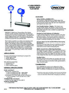
6 Death or permanent injury may result from accidents with these systems.! This guide is the basic reference tool for all ONICON TURBINE Flow meters . If you have not purchased all of the options, there will be references in this manual which are not applicable to your METER (s). TYPICAL TURBINE FLOW METERSONICON s TURBINE Flow meters measure the velocity of flowing liquids by counting the frequency at which the blades of a rotating TURBINE pass a fixed electrode. Circuitry within the flow METER electronics enclosure then converts the rotational rate to digital and/or analog signals which are transmitted via a connecting cable to any of ONICON s display devices, Btu meters and/or a data acquisition or NPTP rocess ConnectionsElectronics EnclosureInline MeterInsertion Meter11451 Belcher Road South, Largo FL 33773 USA Tel +1 (727) 447-6140 Fax +1 (727) 442-5699 Flow METER Manual 04/16 - 0721-6 / 13518 Page STANDARD FEATURES AND SPECIFICATIONS(Refer to specification sheet for particular model to obtain additional details)ACCURACYI nsertion meters OF READING at calibrated velocity 1% OF READING from 3 to 30 ft/s (10:1 range) 2% OF READING from to 20 ft/s (50:1 range)Inline meters OF READING at calibrated velocity 2% of reading from to 38 GPM (50.)
7 1 range)Sensing Method Single- TURBINE meters Single TURBINE electronic impedance sensing (non-magnetic and non-photoelectric)Dual- TURBINE meters Dual TURBINE electronic impedance sensing (non-magnetic and non-photoelectric) and frequency averaging Size Range Single- TURBINE Insertion meters 1 through 72 nominalDual- TURBINE Insertion meters 2 through 72 nominalInline meters or 1 NPT threaded or copper sweat process connectionsSupply Voltage 24 4 V AC/DC at 80 mA Liquid Temperature Range Standard: 180 F continuous, 200 F peak High Temp: 280 F continuous, 300 F peak Insertion meters operating above 250 F require 316 stainless steel construction optionAmbient Temperature Range -5 to 160 F (-20 to 70 C)Operating Pressure 400 PSI maximumPressure Drop Insertion meters Less than 1 PSI at 20 ft/s in 2 pipe, decreasing in larger pipes and lower velocitiesInline meters 3 PSI at maximum flow rateMaterial Insertion meters Wetted metal components Standard: Electroless nickel plated brass Optional: 316 stainless steelInline meters Brass sensor body Electronics Enclosure Standard: Weather-tight aluminum enclosure (NEMA4) Optional: Submersible enclosure (NEMA6)Electrical Connections Standard: 10 of PVC jacketed cable with NPT conduit connection Optional: Indoor DIN connector with 10 of plenum rated cableOutput Signal(s) Standard.
8 Calibrated frequency output 0-15 V pulse Optional: Analog, Iso Analog, and scaled pulse outputs also available, based on modelApprovalsOptionalFor F-1100 / F-1200 Series Only, maximum temperature 180 F (82 C) TURBINE INSERTION FLOW METERNSF/ANSI 61 <MH60590>ALSO CLASSIFIEDIN ACCORDANCE WITHNSF/ANSI 37211451 Belcher Road South, Largo FL 33773 USA Tel +1 (727) 447-6140 Fax +1 (727) 442-5699 Flow METER Manual 04/16 - 0721-6 / 13518 Page ADDITIONAL REQUIRED HARDWAREAll ONICON insertion type meters can be installed and removed via a 1 or larger full port ball valve without stopping flow. The terms Standard and Hot Tap refer to the Installation method of the isolation valve kit Installation Hardware: For new construction or scheduled shutdown; once kit is installed, the flow METER can be installed or removed without system Tap Installation Hardware: For applications which require the access hole in the pipe to be drilled through the valve using a wet tap drilling machine, while the hydronic system is pressurized and : Installation hardware materials vary greatly based on pipe material, pipe size and standard vs.
9 Hot tap MODEL NUMBERING SYSTEMF-XX YY SERIES OUTPUT SIGNALF-11 Single TURBINE , Insertion Type F-12 Dual TURBINE , Insertion Type F-13 Inline TURBINE METER Example: F-1210 = Dual TURBINE , analog and frequency outputs 00 Frequency Output (15 V pulse) For connection to ONICON display or BTU METER only. 10 Analog Output (non-isolated) Provides 4-20 mA, 0-10 V and 0-5 V outputs. Most commonly used output type. Frequency output also available. 11 Isolated Analog OutputProvides 4-20 mA, 0-10 V and 0-5 V outputs. Signal ground is isolated from power supply and pipe ground. Frequency output also Output (non-isolated)Provides isolated dry-contact scaled pulse.
10 Example: 1 pulse = 10 gallons. Frequency output also available. WARRANTY AND SERIAL NUMBERW arranty ONICON s complete warranty is included in Appendix C of this manual as a part of the Conditions of Sale. meters purchased after November 1, 2000 include a two-year No fault warranty which may cover accidental damage caused during Installation or start Number The serial number of your flow METER is located on a label on the side of the electronics enclosure. The model number is also listed on this label. The serial number is a unique identifier that you should refer to, along with the model number, whenever you contact ONICON for assistance regarding your Belcher Road South, Largo FL 33773 USA Tel +1 (727) 447-6140 Fax +1 (727) 442-5699 Flow METER Manual 04/16 - 0721-6 / 13518 Page 7 SECTION : UNPACKINGT urbine flow meters are generally shipped in one package unless optional hardware or equipment is ordered.


