Transcription of ture 300°C for 2hr, 400°C for 2 hour Circular Long …
1 18. 08. 20. Document Number 6711561 Nuaire | Western Industrial Estate | Caerphilly | CF83 1NA | Directive 2014/35/EUAXLong Cased axial FansHigh Temperature 300 C / 400 C for 2 hours Installation ManualEMC Directive 2014/30 Hazard Symbols GENERAL WARNING Signifies a general warning regarding hazard specified by supplementary information. ELECTRIC SHOCK This unit must be completely electrically isolated before any panels are removed. Check mains supply and control connections. ROTATING PARTS This unit contains fast moving rotational parts which may start automatically. It is the sole responsibility of the installer to adequately guard these components. REFER TO INSTRUCTION MANUAL Read and understand the installation and maintenance manual before installing, operating or maintaining this SAFETY INFORMATION The provision of the electrical supply and the connection of the unit to the mains must be carried out by a qualified electrician.
2 Isolate from power supply before removing any covers. During installation / maintenance ensure all covers are fitted before switching on the mains supply. All-pole disconnection from the mains as shown in the wiring diagram must be incorporated within the fixed wiring and shall have a minimum contact separation of 3mm in accordance with latest edition of the wiring regulations. This unit must be earthed. Ducting must be securely fixed with screws to the spigot to prevent access to live parts. Duct runs terminating close to the fan must be adequately protected by suitable guards. If the supply cord is damaged, it must be replaced by the manufacturer, its service agent or similarly qualified persons in order to avoid a hazard. Precautions must be taken to avoid the back-flow of gases into the room from the open flue of gas or other fuel-burning appliances. This appliance should not be used by children or persons with reduced physical, sensory or mental capabilities or lack of experience and knowledge, unless they have been given supervision or instruction concerning the safe use of the appliance by a person responsible for their safety.
3 Children shall not play with the appliance. Cleaning and user maintenance shall not be carried out by 08. 20. Document Number 6711562 Nuaire | Western Industrial Estate | Caerphilly | CF83 1NA | Important InformationThis manual contains important information on the safe and appropriate assembly, transport, commissioning, operation, maintenance, disassembly and simple troubleshooting of the the product has been manufactured according to the accepted rules of current technology, there is still a danger of personal injury or damage to equipment if the following general safety instructions and the warnings contained in these instructions are not complied with. Read these instructions completely and thoroughly before working with the product. Keep these instructions in a location where they are accessible to all users at all times. Always include the operating instructions when you pass the product on to third Personal Protective EquipmentThe following minimum Personal Protective Equipment (PPE) is recommended when interacting with Nuaire product: Protective Steel Toed Shoes - when handling heavy objects.
4 Full Finger Gloves (Marigold PU800 or equivalent) - when handling sheet metal components. Semi Fingerless Gloves (Marigold PU3000 3DO or equivalent) - when conducting light work on the unit requiring tactile dexterity. Safety Glasses - when conducting any cleaning/cutting operation or exchanging filters. Reusable Half Mask Respirators - when replacing filters which have been in contact with normal room or environmental would always recommend a site specific risk assessment by a competent person to determine if any additional PPE is required. INTRODUCTIONN uaire's Axus range of Long Cased axial Flow fans with one off high temperature operation are produced in sixteen case sizes from 315mm diameter to 1600mm diameter with duties up to 65m3 are manufactured in aluminium alloy or steel. These high performance impellers have been selected to provide a range of units that will suit your specific requirements. Note: Nuaire will not accept responsibility for damaged units when unauthorised personnel have altered blade angles.
5 The fans are available for three phase operation units are designed for: S1 DUTY Day to day operation and in the event of fire a one off emergency range has been designed for ease of installation into new or existing ductwork systems. The optional supporting brackets can be located any where around the circumference of the flange allowing the fan to be installed in any mounting plane. Fan units are suitable for internal and external Mounting kits are available as an ancillary. A full range of additional ancillaries is available including: Matching flanges, matching attenuators, mounting brackets, flexible connectors, inlet cones and backdraught compliant, refer to EC certificate of conformity, Code Description: AX 63 AD - 2 1 A 7 + 13M | | | | | | | | | | 1 2 3 4 5 6 7 8 9 10 1. Range: Long Case axial fans 2. Impeller Size (cm): 31 to 160 3. Impeller Reference: Contact Nuaire 4.
6 Guide Vanes: * = Guide Vanes - = No Guide Vanes 5. Motor Poles: 2, 4, 6 or 8 6. Blade Angle Reference: Contact Nuaire 7. Impeller Material: A = Aluminium S = Steel 8. Motor Type: 7 = Three Phase 300 C/2hr 8 = Three Phase 400 C/2hr 9. Speed Control: + = Must Be VSD Controlled - = No Speed Control 10. Further Options: Contact Nuaire DELIVERY & HANDLINGAll equipment is inspected prior to despatch and leaves the factory in good condition. Upon receipt of the equipment an inspection should be made and any damage indicated on the delivery note. Particulars of damage and/or incomplete delivery should be endorsed by the driver delivering the goods before offloading by the responsibility will be accepted for damage sustained during the offloading from the vehicle or on the site thereafter.
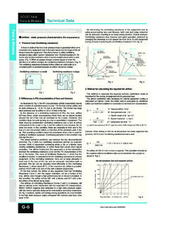
7 All claims for damage and/or incomplete delivery must be reported to Nuaire within two days of receipt of the fan impeller is carefully balanced and centralised in the fan case, it is therefore essential that great care is exercised when handling the unit. Check the weight on the rating plate details before attempting to lift and always use a spreader as shown (Figure 1), never pass lifting slings through the must be taken when handling a unit/attenuator assembly fitted with flexible connectors as the connectors can be distorted or Unit INSTALLATION Installation must be carried out by competent personnel, in accordance with good industry practice, the appropriate authority and in conformance with all statutory and governing regulations IEE, CIBSE, COSHH, HVCA, ATEX, BSI & EN standards commencing installation check that all material, including optional ancillaries are available to complete the installation. Every unit is tested and serialised at works and a test certificate produced, the details recorded on the fan side rating plate should also be referred to before handling and 08.
8 20. Document Number 6711563 Nuaire | Western Industrial Estate | Caerphilly | CF83 1NA | Manual L1 L2 L3 400V 3 phase 50Hz supply380V 3 phase 60Hz supply460V 3 phase 60Hz supplyFanunit2 Wiring - Single Speed - Three Phase (3kw and below) Two Speed - Dual Wound Motor ( Starting Both Speeds) - Three Starting (3kW and below) - Three PhaseL1L2 LowSpeedHighSpeedL3L1L2L3460V 3 phase 60Hz supply 380V 3 phase 60Hz supply 400V 3 phase 50Hz supply 1U1V1W2U2V2 WMotorterminalbox460V 3 phase 60Hz supply 380V 3 phase 60Hz supply 400V 3 phase 50Hz supply L1L2L3 STARL1 - U1L2 - V1L3 - W1 Link W2, U2, V2U1V1W1W2U2V23 4 Wiring - Two Speed - Dual Wound Motor - Three PhaseWiring - Starting (3kW and below) - Three PhaseAny damages or deviations should be immediately reported to the seller/supplier/agent quoting the order and product details from the product rating not reverse impeller direction of operation as performance of the unit is drastically reduced.
9 Do not alter the blade angle of impeller without the permission of Nuaire, doing so may invalidate your Mechanical InstallationRotate the fan impeller by hand to ensure free and smooth rotation and that no transit or handling damage has occurred, observe the direction of flow/direction of rotation arrow and ensure that: All optional accessories such as support brackets, attenuators, inlet cones, guards, flexible connectors etc. are assembled to the fan. AV mounts isolate the fan only. Attenuators, backdraught dampers and other significant mass accessories should form part of the fixed ductwork after the flexible connection. The optional support brackets are correctly fitted, at any position around the circumference, but suit the installation plane. External termination box is accessible to the electrician. When offering the fan to the ducted system that both inlet and outlet connections are perfectly aligned. In order to ensure performance is as stated, a minimum distance of twice the fan diameter is required between the appliance and any bends in the Horizontal on Floor or Supported from Wall resilient mountings should be attached to the unit mounting brackets at this stage.
10 If the unit is supported from a wall, supporting brackets should be used. Position and align the unit with the ductwork in both horizontal and vertical planes and pack height under mounting feet if , anti-back draught dampers form part of the fixed ductwork after the flexible Suspended Horizontally or VerticallyAnti-Vibration ( ) mounts must be arranged so that they are used in compression only. A suspended steel under frame would be necessary (by others) to support the unit, standing on Electrical MotorsMotors are totally enclosed and protected to IP55 (Dust and low pressure water jets). Motors comply with BS5000, EN600034 and motors have sealed for life ball bearings in units up to 132mm frame size. For frame sizes of 160mm and above motors are of the re-greaseable type. Enclosures are to IP55 with class H insulation. Motors are tested in accordance with note the requirements for maintenance of the motor. Failure to comply with the recommendations will invalidate any warranty WiringElectrical supply wiring connection is to an externally mounted terminal box on the case exterior.