Transcription of Two screw pumps
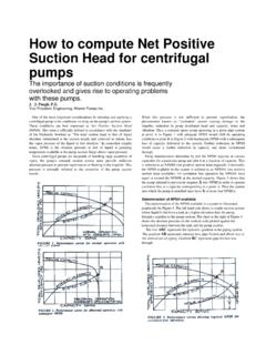
1 Reprint from PetroMin October Issue 1994In multiple screw pumps , each wrap of screw threadeffectively forms a stage of pressure capability. Highpressure pumps have 5 to 12 stages or wraps, whereaslow pressure pumps may have only 2 or 3 wraps. Thepresure capability of a two screw pump, for example,is illustrated in Figure 1. 90 degrees from the plane of the the axial direction, discharge pressure acts on the exposedcenter areas of each screw set. Because the diameters and leadangles of the opposed screw sets are equal, hydrostatic forcesacting to the left are equal to those acting to the right. The net axialforce due to discharge pressure is zero and the screw shafts are screw pumpsThe two screw type pump normally uses timing gears outside ofthe pumped liquid to synchronize the mesh of the non-contacting screws.
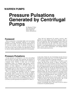
2 The most common arrangement is opposedhelices (double suction) with the flow pattern being from theends of the screw sets to the center of the pump, Figure each wrap of thread , the stage pressure acts on allexposed areas. Due to blanking of some areas by theintermeshed threads, a radially unbalanced area exists withineach stage. Stage pressure acting on these unbalanced areascause radial forces on each screw set approximatelyTwo screw pump hydraulic forces: Hydraulic radial forceson a two screw pump rotor due to differential pressure areillustrated in Figure 3. The forces are uniform along the lengthof the pumping threads. These hydraulic forces cause adeflection d", for which running clearance must be provided inthe surrounding pump body.
3 Greater deflection requires largerclearances resulting in more slip flow or volumetricinefficiency, so d" must be kept to a minimum. Excessivedeflection will cause damage to the surrounding body and/orcontribute to rotating bend fatigue, which will ultimately resultin shaft breakage. The following is the general form of thedeflectionequation:d = F x L3 I c / x E x Iwhere F is the summation of thehydraulic forces, L is the bearing span, cis a constant, E is the shaft materialmodulus of elasticity and I is the shaftmoment of inertia. The shaft moment ofinertia is a function of its diameter, equation is simplified and, inpractice, must account for the varyingshaft and screw diameters as they changealong the length of the rotor.
4 If screw "shells" are not integral with the shaft,that is, not made from a single piece ofmaterial, then material differences as wellas attachment schemes must be factoredinto the deflection calculation. In anyevent, it is easy to see that the bearingspan, L, must be kept to a minimumto minimize deflection. Also of greatimportance, is the use of large diametershafts and screw root sections to maintainminimum that twin screw pumping screwswill have either one or two thread single thread start sets displace morevolume per revolution but form fewerstages within a given body length. Doublethread start screw sets displace lessvolume than single starts but form morestages in the same body length and arethus suitable for higher pressures.
5 Doublethread start rotors are also inherently indynamic balance due to their radial masssymmetry. Single thread start rotor setsmust normally be dynamicallybalanced using dynamic balancemachines and removing excess mass bydrilling radial holes in the outsidediameters of the screw on the direction in which thethreads are machined (left or right hand)and the direction of shaft rotation, thepump manufacturer can cause the de-flection to be in either of the two radialdirections, up or down for a horizontalpump. These radial deflection loads areabsorbed through externally lubricatedanti-friction bearings. Radial loads areproportional to differential pressureacross the pump.
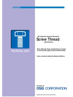
6 Higher differentialpressure produces higher radial loads orforces. Smaller lead angles of the screwset reduce these radial loads as well asreducing the flow rate. Larger lead anglesincrease the flow rate as well as the radialloading. Bearings are usually sizedto provide 25,000or more hours L1O bearing life atmaximum allowable radial loadingand maximum design operatingspeed. Because of this pumpage-independent bearing system, twoscrew pumps with external timinggears and bearings can handle highgas content as well as light oilflushes, water, screw pumpsThree screw pumps are producedin two basically different designs,single ended and double double end (double suction)design, Figure 4, is balanced in theaxial direction in exactly the samemanner as a two screw pump.
7 Theareas and lead angles are equal andopposite so that the axial hydro-static forces on the shaftsare opposed resulting in zero axial forcedue to discharge pressure. Virtually allthree screw pipeline pumps use twothread starts on each of the rotors whichprovides inherent dynamic ended pumps use two 51-milarbut different techniques to accomplishaxial hydraulic balance. The center screw ,called a power rotor, incorporates abalancing piston at the discharge end ofthe screw thread , Figure 5. This pistoncan be an integral part of the shaftmaterial (one piece) as illustrated, ashrink fitted piece or a replaceable, hardcoated piston. The area of the piston ismade aboutl5% greater than the crosssectional area of power rotor inter-meshing exposes more than360 degrees of the power rotor thread todischarge greater balance piston areacompensates for the extra exposed threadarea.
8 Consequently, equal opposingforces produce zero net axial force due todischarge pressure and place the powerrotor in tension. The balance pistonrotates within a close clearance stationarybushing which may also be hardened orhard coated to resist erosive wear due tosand content in crude oil. The drive shaftside of the piston is normally internallyor externally ported to the pump inletchamber. Balance leakage flow acrossthis running clearance flushes the pumpmechanical seal, which remains atnominal pump inlet screw pump idler rotors:The twoouter screws, called idler rotors, alsohave their discharge ends exposed todischarge pressure. Through variousarrangements, discharge pressure isintroduced into a hydrostatic pocket areaat the inlet end of the idler rotors, Figure6.
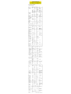
9 The effective area is just slightly lessthan the exposed discharge end area,resulting in approximately equalopposing axial forces on the idler idler rotors are therefore incompre~~ion with a dcllbcrate imbalanceto maintain their runnin~ position towardthe inlet endof the pump. Should any force cause theidler rotor to move toward discharge, aresulting loss of pressure acting on thecup shoulder area or hydrostatic landarea tends to restore the idler rotor to itsdesign running position. The upper viewin Figure 6 shows a stationary thrustblock (cross hatched) and a stationary,radially self locating balance pressure is brought into thecup via internal passages within thepump or rotor itself.
10 The lower viewshows a hydrostatic pocket machinedinto the end face of the idler rotor. It, too,is fed with discharge pressure. Figure 7illustrates the pressure gradient acrossthe inlet faces of the idler rotors. The gapshown is exaggerated and is actually verynear zero. Diameter K2 is approximately50% of diameter K Discharge pressureintroduced into the hydrostatic pocketacts on the full area of K~. This pressurethen breaks down in a nonlinear manneras balance flow escapes into the inletchamber across the land diameter, K1-K2. On average, half the dischargepressure acts on the land area. Thedeveloped force opposing that ofdischarge pressure, P, acting on the idlerdischarge area is:P (K2)2/4 + P/2( /4(K1)2-(K2)2)The force calculated above is slightly lessthen the force developed by dischargepressure acting on the exposed dischargearea of the discharge end of the idlerrotor.