Transcription of TX9600TS ENG Manual (Page 1) - LUX Products
1 TX9600TS . SMART TEMP UNIVERSAL. 7-DAY PROGRAMMABLE TOUCHSCREEN THERMOSTAT. (FOR BOTH CONVENTIONAL AND HEAT PUMP SYSTEMS). I N S TA L L AT I O N A N D O P E R AT I N G I N S T R U C T I O N S. 52106. IMPORTANT! Please read all of these instructions carefully before beginning installation. Label every wire terminal designation on your existing thermostat wiring before removing your old thermostat. Ignore the color of the wires since they may not comply with any standard. Please connect wires using the terminal letter designations. Thank you for your confidence in our product. To obtain the best results from your investment, please read and follow the installation procedures carefully, and one step at a time. This will save you time and minimize the chance of damaging either the thermostat or possibly your heating and cooling system.
2 These instructions may contain information beyond that which may be required for your particular installation. SYSTEM COMPATIBILITY .. 2 COMPLETE THE INSTALL .. 19. FEATURES .. 3 FRONT PANEL ITEMS .. 19. TOOLS YOU MAY NEED .. 3 OPERATING INSTRUCTIONS .. 20. MOUNTING LOCATION .. 4 TEMPERATURE PROGRAMS .. 23. REMOVE OLD THERMOSTAT .. 4 ADVANCED FEATURES .. 24. INSTALL THERMOSTAT BASE .. 5 BATTERY REPLACEMENT .. 32. WIRING INFORMATION .. 6 TECHNICAL ASSISTANCE .. 33. WIRING DIAGRAMS .. 8 LIMITED WARRANTY .. 33. HARDWARE SETUP OPTIONS .. 17 MERCURY NOTICE .. 33. WARNING: Use Energizer or DURACELL Alkaline Batteries Only. Energizer is a registered trademark of Eveready Battery Company, Inc. DURACELL is a registered trademark of The Gillette Company, Inc. 2011 LUX Products CORPORATION. ALL RIGHTS RESERVED. TX9600TS .
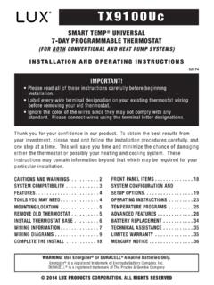
3 Fan Mode Switch Menu LUX. FAN. Button MENU AUTO. ON. PM F F. SET. HEAT. Clock OFF. COOL. System Mode Switch Room Temperature Set Temperature SYSTEM COMPATIBILITY: The electrical rating for this thermostat is Amps per terminal, with a maximum total combined load of for all terminals combined. COMPATIBLE WITH: Most 24-volt heating and cooling systems 1 or 2 stage Heat / 1 stage Cool: Gas, Oil or Electric systems 1 or 2 stage Heat / 1 stage Cool: Heat Pump systems 3-wire hydronic (hot water) zone valves Gas Millivolt heaters NOT COMPATIBLE WITH: 120/240 VAC line-voltage systems (without a transformer), ask your LUX. dealer for thermostats to control these systems. 2. FEATURES: 1 or 2-Heat / 1-Cool, 7-day programming Universal Compatibility for all system types Each day of the week can be programmed separately Easy to use, touchscreen menu operation User-selectable periods per day (2 or 4).
4 User-selectable programmable or non-programmable operation LuxLight EL (Electro-Luminescent) lighted display Energy usage monitor Programmable air filter life timer Programmable keypad lockout for unauthorized users Manual temperature hold Adjustable vacation hold (1 to 30 days). Temporary temperature override Adjustable temperature differential / cycle-rate Adjustable 2nd heat stage Offset setting User temperature calibration Adjustable heat/cool set temperature limit stops Smart recovery Dual-powered (battery and/or 24-volt system powered). Battery-free memory storage F/C temperature display 12/24-hour clock display 5/2-minute selectable time delay for equipment protection TOOLS YOU MAY NEED: Screwdrivers Wire Stripper Wire Cutter Drill with assorted drill bits (new installations only). 3. MOUNTING LOCATION: On replacement installations, mount the new thermostat in place of the old one unless the conditions listed below suggest otherwise.
5 On new installations, please follow these general guidelines: 1. Mount the thermostat on an inside wall, about 5 ft. ( ) above the floor. 2. Do not locate the thermostat where air circulation is poor such as in a corner, alcove, or behind a door that is normally left open. 3. Do not locate the thermostat where unusual heating or cooling conditions may be present, such as: direct sunlight, above a lamp, television, or radiator, or on a wall next to an exterior door or window. 4. Do not locate in a damp environment, as this can lead to corrosion that may shorten thermostat life. 5. If painting or construction work is still ongoing, cover the thermostat completely or wait until this work is complete before installation. WARNING: All wiring must conform to the local codes and ordinances that are in your particular location.
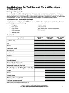
6 REMOVE OLD THERMOSTAT: 1. Turn OFF the electricity to all heating and cooling components. Do not turn the electricity back on until all work is completed. 2. Remove the front portion of your old thermostat to expose the wiring connections. OFF. 3. Write down the letters printed near each wire terminal that is used, and also the color of each wire that is connected to it. Self-adhesive wire labels are also enclosed. 4. Carefully remove the wires one at a time, and bend them in a manner so that they do not fall back inside the wall. Do not allow bare wire ends to touch each other. 5. Loosen the mounting screws for the old thermostat and carefully remove it from the wall. 4. INSTALL THERMOSTAT BASE: Large Indentation: Front Housing Release Mode Switches THERMOSTAT TOP VIEW. 1. Strip wire insulation leaving only 3/8 in.
7 ( ) bare wire ends, and clean off any corrosion present. 2. Fill the wall opening with non-combustible insulation to prevent drafts from affecting the thermostat's normal operation. 3. Route the wires through the opening in the new thermostat base plate, and hold the base against the wall. Try to line up the screw holes from the prior thermostat, and install the mounting screws. 4. If the previous holes cannot be used, hold the thermostat base against the wall so that it appears straight and level (position the base for best appearance) and mark for the new screw holes. Attach the base to the wall using the screws provided (use the supplied plastic anchors if needed when mounting to a soft material such as drywall). 5. WIRING INFORMATION: CONNECTING THE WIRES: When attaching the wires to the thermostat, please ensure that the bare wire ends are held ALL the way into the terminal block while the screw is being tightened.
8 WIRING BASE PLATE NOTICE: This thermostat model is part of a family of similar models that have the same general visual appearance. Even though this base plate may look the same as base plates from other models, the wiring connections may have different terminal letters for different purposes. Please do not interchange the back plates and/or thermostat front halves of other similar looking models. Doing so may cause undesired heating and/or cooling operation to occur. 6. WIRING DIAGRAM NOTES: (Important, please read all notes before connecting wires). If the information provided in the following wiring diagrams does not clearly represent or match your system, please refer to the TECHNICAL. ASSISTANCE section of this Manual , and contact us before removing any of your existing thermostat wiring. All of the dashed wires shown in the wiring diagrams are either optional, or their usage depends upon your specific system type or brand.
9 For example: Diagram #1 shows the fan wire as optional. If your system does not have a fan, than this terminal will not be used. Terminal letters shown in black represent typical wiring applications. Depending upon the brand of your specific system or thermostat, your terminal letters may not match exactly. Terminal letters shown in gray represent other possible wiring designations that you might see on your existing thermostat terminals. The optional C terminal is used for powering the thermostat by the 24- volt system, using the System Common wire. This can be used alone, or in addition to installing batteries as a backup. NOTE: connecting the System Common wire to the thermostat is not necessary for heating and cooling to function properly. If your old thermostat has both a Y and C wire present, then C is most likely a System Common wire.
10 For Heat Pump systems, you will use either the O terminal or the B . terminal on this thermostat, but not both. If your old thermostat has both an O and a B wire present, then B is likely a System Common wire and may be connected to the C terminal. Connecting a System Common wire to this thermostat's B terminal may damage the thermostat, and also your heating and cooling system. Some Heat Pump systems have a wire for AUX electric heat (usually W2), and also a separate wire for Emergency electric heat (usually E). This thermostat uses the W2 terminal for both AUX and Emergency Heat. Tape off your E wire, and confirm that all components function without it. If replacing an old thermostat that has a mechanical clock, there may be two wires labeled as C for the clock power. Tape off these wires and do not connect them to the C terminal of this thermostat.