Transcription of typical sport aircraft electrical systems - Microair
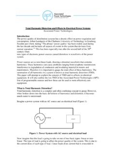
1 typical aircraft electrical systems 15th March 2006 Microair Avionics Pty Ltd ABN 92 091 040 032 P O Box 5532 Airport Drive Bundaberg West Queensland 4670 Australia Phone: Fax: Email: Web: 07-41553048 +61 7 41553048 07-41553049 +61 7 41553049 Microair Avionics Introduction There are some important do s and don t s when considering the electrical system of an aircraft . Even in cases where the aircraft kit manufacturer has supplied the hardware for the electrical system in the kit, there is often a need to customise the system to better suit the individuals tastes, or the requirements of extra equipment. electrical Load Most aircraft builders/owners will possess a multi-meter, and will be familiar with how to measure the voltage at various points in the electrical system .
2 A voltage measurement by itself does not however determine the LOAD at that point. To do this the current must be measured. Most multi-meters will do this, but to take the measurement, the circuit must be opened, and the multi-meter inserted in series with the circuit. The electrical load must be known to build the electrical system from the correct materials. Wiring has a load rating normally quoted as a maximum number of AMPS. Switches and circuit breakers also have load ratings in their specifications. IMPORTANT It is vital that the components of your electrical system have load ratings which exceed the worst case electrical load which the components are expected to bear. If the electrical load draws 5 Amps, then the wiring must be rated above 5 Amps.
3 Wiring Wiring is usually described in terms of its gauge . The most commonly used scale is American Wire Gauge (AWG). This scale has a corresponding electrical load rating. Before you can determine the appropriate AWG for the various lines in your electrical system , the length of each wire must be considered. is an advisor circular issued by the FAA, which has grown over the years to become a substantial book of how to repair most types of airframe. Section 13 describes the wiring needs for aircraft systems , and relates the electrical load a wire must bear, to the maximum length over which it is safe for that wire to carry such a load. It is possible for small wires to carry large currents for short lengths, the longer the length required the larger the wire gauge must become.
4 You need to consider: What is the load on the wire ? What is the length of the wire ? ..and from this What should the gauge of the wire be ? Microair Avionics Pty Ltd ABN 92 091 040 032 P O Box 5532 Airport Drive Bundaberg West Queensland 4670 Australia Phone: Fax: Email: Web: 07-41553048 +61 7 41553048 07-41553049 +61 7 41553049 Microair Avionics Insulation electrical wire is clad in insulation. Most people will be familiar with conventional plastic insulation which is in common use in houses, cars, boats etc. aircraft present a unique situation which the above applications don t have. In the case of a fire, you cannot run away, you cannot follow an evacuation plan (unless you are wearing a parachute). You are forced to stay at the scene of the fire until you can land, or extinguish the fire.
5 Where there is fire there is All things burn, it just depends on the required temperature. Once on fire, all things give off smoke or fumes. The smoke and fumes in most cases are toxic in concentrated quantities. If you are trapped in an enclosed cockpit at the scene of a fire, there is a serious risk of being asphyxiated by the smoke or fumes. It is very important to select wire with an insulation which resists fire, does not support the spread of fire, and most importantly, does not give off smoke or fumes. There are a variety of lesser known MIL-Spec wires which have been designed with very high fire ratings. Most comply with Military Specification M22759/16-xx where the xx is the AWG size of the wire.
6 This wire spec is available in 10 colours including white. Colour Code Most General Aviation (GA) aircraft are wired with white wire. The wiring is typically labelled at regular intervals to make identification easy. The single colour option can save money, because you can order a larger quantity of just one part number, instead of small quantities of many part numbers. Despite this, Microair recommends that you establish a colour code for your aircraft and stick to it. By the time you have finished wiring the instrument panel in a single colour you will be struggling to identify one wire from another. Many Avionics manufacturers offer a colour code in their installation manuals. Microair recommends that you follow their advice.
7 It can be very expensive in some cases to cross wires over, and then turn the unit on. We have a large number of sad stories on file, which have this scenario as a theme. The most common of all colour codes is: Red positive Black negative Microair Avionics Pty Ltd ABN 92 091 040 032 P O Box 5532 Airport Drive Bundaberg West Queensland 4670 Australia Phone: Fax: Email: Web: 07-41553048 +61 7 41553048 07-41553049 +61 7 41553049 Microair Avionics Fusing All electrical systems require protection from fault currents. High currents will cause heat, and possible fire, hence a safety device should always be used. aircraft fusing should first consider the output from the engines alternator to the instrument panel (not the starter motor).
8 If the alternator can deliver approx 30A, then the primary or master fuse should be at least 30A. The master fuse is installed in series with the master switch. If the master fuse blows, everything loses power! From the master switch and fuse, the power is fed on to a bus (typically a brass or aluminium bar with thread terminal studs). From this bus, individual power feeds are run first to a circuit breaker, and then on to the application (eg ETC). The rating of the circuit breaker should be determined by considering the maximum current requirements of the application. An ETC can draw up to in operation. Fuses or circuit breakers are normally a minimum of twice the typical current draw. Hence the ETC would have a 5A circuit breaker.
9 Be careful when researching the maximum current requirements. A radio will draw only a few 100mA on receive, but can draw amps when transmitting. Transponders typically draw only 250mA, but their encoders can draw nearly an amp. Be wary of two applications sharing the same fuse / circuit breaker. If one application faults and blows the fuse / circuit breaker, you lose both applications. Pairing up a transponder and encoder will not cause you any problem, but putting your radio and GPS together may not be a good idea. Avionics require special attention. Avionic applications are typically split off on to their own power bus. It is very desirable for the power fed from the main bus to the avionics bus to pass through a power filter, and an avionics master switch.
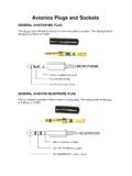
10 The switch allows the pilot to turn off all avionics before engine start up and shutdown. There are moments when the engine s electrical system can give out large voltage spikes which could damage your avionics. Applications which should be powered from the avionics bus: Radio Intercom Transponder Altitude encoder GPS EFIS systems Autopilot Applications which should NOT be powered from the avionics bus: ETC (and other gyro instruments) EMS systems Strobes Lighting Fuel pumps electrical flap drives Microair Avionics Pty Ltd ABN 92 091 040 032 P O Box 5532 Airport Drive Bundaberg West Queensland 4670 Australia Phone: Fax: Email: Web: 07-41553048 +61 7 41553048 07-41553049 +61 7 41553049 Microair Avionics BNC (1/4") (1/8") (1/16")Step 1 Step 2 Step 3 Step 4 Terminations The most important consideration when selecting a termination method, is VIBRATION.