Transcription of ELECTRICAL SYSTEMS - boatfix.com
1 4E72938 ELECTRICAL SYSTEMSWIRING DIAGRAMS4E - 0 - WIRING DIAGRAMS90-816462 2-695 Table of ContentsPageWiring Colors for MerCruiser4E - 1.. Wiring Diagrams4E - 2.. Engine Wiring Diagram (Breaker Points Ignition)4E - 2.. Engine Wiring Diagram (DDIS Ignition)4E - 3.. Engine Wiring Diagram (EST Ignition)4E - 4.. Instrumentation Wiring Diagram (Battery Meter Circuit)4E - 5.. Instrument Wiring Harness4E - 7.. Breaker Point Ignition - Dual Station Using A Neutral Safety Switch In Only One Remote Control4E - 7.. EST and DDIS ignition - Dual Station Using A Neutral Safety Switch In Only One Remote Control4E - 8.. PageBreaker Point Ignition - Dual Station Using A Neutral Safety Switch In Both Remote Controls4E - 9.. EST and DDIS Ignition - Dual Station Using A Neutral Safety Switch In Both Remote Controls4E - 10.. Battery Meter Gauge4E - 11.. Cruiselog4E - 11.. Fuel Gauge and Sender4E - 11.. Audio Warning System4E - 12.
2 Water Temperature Gauge4E - 12.. Oil Pressure Gauge4E - 12.. Clock4E - 12.. 4E - WIRING DIAGRAMS90-816462 2-695 WIRING DIAGRAMS - 4E - 190-816462 2-695 Wiring Colors for MerCruiserBIA COLOR CODE AND ABBREVIATIONSWHERE USEDBLACK (BLK)All GroundsBROWN (BRN)Reference Electrode-MerCathodeORANGE (ORN)Anode Electrode-MerCathodeLIGHT BLUE/WHITE (LIT BLU / WHT)Trim- Up SwitchGRAY (GRY)Tachometer SignalGREEN/WHITE (GRN / WHT)Trim - Down SwitchTAN (TAN)Water Temperature Sender to GaugeLIGHT BLUE (LIT BLU)Oil Pressure Sender to GaugePINK (PNK)Fuel Gauge Sender to GaugeBROWN/WHITE (BRN / WHT)Trim Sender to Trim GaugePURPLE/WHITE (PUR / WHT)Trim- Trailer SwitchRED (RED)Unprotected Wires from BatteryRED/PURPLE (RED / PUR)Protected (Fused) Wires from BatteryRED/PURPLE (RED / PUR)Protected (+12V) to Trim PanelORANGE (ORN)Alternator OutputPURPLE/YELLOW (PUR / YEL)Ballast BypassPURPLE (PUR)Ignition Switch (+12 V)YELLOW/RED (YEL / RED)
3 Starter Switch to Starter Solenoid to Neutral StartSwitch4E - 2 - WIRING DIAGRAMS90-816462 2-695 Wiring Engine Wiring Diagram (Breaker Points Ignition)50726 CHOKESHIFTINTERRUPTSWITCHALTERNATOROPTIO NAL AUDIOWARNING WATER TEMPERATURE HEATSWITCHWATERTEMPERATURESENDEROPTIONAL OILPRESSURESWITCHTERMINALBLOCKENGINEGROU ND GROUND STUD ONENGINE FLYWHEELHOUSING GROUND SCREW ONINNER TRANSOMPLATE CIRCUITBREAKERSTARTER SLAVESOLENOIDTRIMSENDEROIL PRESSURESENDERWIRING DIAGRAMS - 4E - 390-816462 Engine Wiring Diagram (DDIS Ignition)50727 WATERTEMPERATURESENDERALTERNATORCHOKESHI FTINTERRUPTSWITCHTERMINALBLOCKENGINEGROU ND GROUND STUD ONENGINE FLYWHEELHOUSING GROUND SCREW ONINNER TRANSOMPLATE CIRCUITBREAKEROIL PRESSURESENDEROPTIONAL OILPRESSURESWITCHSTARTER SLAVESOLENOIDTRIMSENDEROPTIONAL AUDIOWARNING WATER TEMPERATURE HEATSWITCH4E - 4 - WIRING DIAGRAMS90-816462 Engine Wiring Diagram (EST Ignition)NEWSTYLEBOTTLEOLDSTYLEBOTTLENOT E 1: Audio Warning system Standard On ModelsNOTE 2: Gray lead for use with service - Ignition ComponentsB - Starting , Charging and Choke ComponentsC - Audio Warning system ComponentsD - Instrumentation ComponentsWIRING DIAGRAMS - 4E - 590-816462 2-695 Instrumentation Wiring Diagram (Battery Meter Circuit)NOTE 1: Connect wires together with screw and hex nut.
4 Tighten securely and coat with Liquid Neoprene to helpcontrol corrosion: when dry, slide neoprene sleeve over 2: Power for a fused accessory panel may be taken from this connection. Load must not exceed 40 ground wire must be connected to instrument terminal that has an 8-gauge BLACK (ground) harness wire connected to 3: Audio warning is standard models and optional on !CAUTIONA udio warning buzzer is not external ignition proof, therefore, DO NOT mount buzzer in engine or fuel PRESSUREWATER TEMPERATUREBATTERY METERAUDIO WARINGBUZZER (OPTIONAL)TRIM INDICATORIGNITION SWITCH20 AMPFUSENOTE 1 & 2 NOTE 1 BLK = BLACKBLU = BLUEBRN = BROWNGRY = GRAYGRN = GREENORN = ORANGEPNK = PINKPUR = PURPLERED = REDTAN = TANWHT = WHITEYEL = YELLOWLIT = LIGHTDRK = DARKE arlier Style Audio Warning Buzzer4E - 6 - WIRING DIAGRAMS90-816462 2-695 NOTE 1: Connect wires together with screw and hex nut.
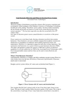
5 Tighten securely and coat with Liquid Neoprene to helpcontrol corrosion: when dry, slide neoprene sleeve over 2: Power for a fused accessory panel may be taken from this connection. Load must not exceed 40 ground wire must be connected to instrument terminal that has an 8-gauge BLACK (ground)harness wire connected to 3: Audio warning is standard models and optional on MeterTo Engine HarnessNOTE 3 TrimIndicatorNOTE 1 NOTE 1 NOTE 274046 Later Style Audio Warning BuzzerWIRING DIAGRAMS - 4E - 790-816462 2-695 Instrument Wiring Harness (Dual Station)BREAKER POINT IGNITION - DUAL STATION USING A NEUTRAL SAFETY SWITCH IN ONLY ONEREMOTE CONTROLFUSEKEY SWITCHWATERTEMPERATUREOILPRESSUREBATTERY METERTACHOMETERPRIMARY STATIONSTART/STOPPANELWATERTEMPERATUREOI LPRESSUREBATTERY METERTACHOMETERSECONDARY STATIONNOTE 2 NOTE 3 NOTE 1 NOTE 4 NOTE 1 NOTE 4 NOTE 4 NOTE 250731 EXTENSION HARNESSTO ENGINEBLK = BLACKBLU = BLUEBRN = BROWNGRY = GRAYGRN = GREENORN = ORANGEPNK = PINKPUR = PURPLERED = REDTAN = TANWHT = WHITEYEL = YELLOWLIT = LIGHTDRK = DARKNOTE 1.
6 BROWN/WHITE wire is taped back at instrument end. If installing on boat that is equipped withMerCruiser Stern Drive, BROWN/WHITE wire is connected to the trim sender terminal block. Also canbe used for an accessory (limit 5 amps).NOTE 2: An accessory fuse panel may be connected at this location. The combined current draw of the primarystation and secondary station MUST NOT exceed 5 3: Tape back and insulate with at least four layers of ELECTRICAL 4: Connect wires together with screw and hex nut. Tighten securely and coat with Liquid Neoprene to helpcontrol corrosion; when dry, slide neoprene sleeve over - 8 - WIRING DIAGRAMS90-816462 2-695 EST AND DDIS IGNITION - DUAL STATION USING A NEUTRAL SAFETY SWITCH IN ONLY ONEREMOTE CONTROL50730 KEY SWITCHWATERTEMPERATUREOILPRESSUREBATTERY METERTACHOMETERPRIMARY STATIONSTART/STOPPANELWATERTEMPERATUREOI LPRESSUREBATTERY METERTACHOMETERSECONDARY STATIONNOTE 2 NOTE 3 NOTE 4 NOTE 1 NOTE 2 EXTENSION HARNESSTO ENGINENOTE 4 FUSENOTE 4 NOTE 1 NOTE 4TO WHT/GRN CONNECTIONON TERMINAL BLOCK ATSHIFT PLATE CUT-OUTSWITCH (ON ENGINEROCKER ARM COVER)NOTE 1: BROWN/WHITE wire is taped back at instrument end.
7 If installing on boat that is equipped withMerCruiser Stern Drive, BROWN/WHITE wire is connected to the trim sender terminal block. Also canbe used for an accessory (limit 5 amps).NOTE 2: An accessory fuse panel may be connected at this location. The combined current draw of the primarystation and secondary station MUST NOT exceed 5 3: Tape back and insulate with at least four layers of ELECTRICAL 4: Connect wires together with screw and hex nut. Tighten securely and coat with Liquid Neoprene to helpcontrol corrosion; when dry, slide neoprene sleeve over DIAGRAMS - 4E - 990-816462 2-695 BREAKER POINT IGNITION - DUAL STATION USING A NEUTRAL SAFETY SWITCH IN BOTH REMOTECONTROLS50735 BLK = BLACKBLU = BLUEBRN = BROWNGRY = GRAYGRN = GREENORN = ORANGEPNK = PINKPUR = PURPLERED = REDTAN = TANWHT = WHITEYEL = YELLOWLIT = LIGHTDRK = DARKFUSEKEY SWITCHWATERTEMPERATUREOILPRESSUREBATTERY METERTACHOMETERPRIMARY STATIONNOTE 2 NOTE 4 NOTE 1 START/STOPPANELWATERTEMPERATUREOILPRESSU REBATTERY METERTACHOMETERSECONDARY STATIONNOTE 2 NOTE 3 EXTENSION HARNESSTO ENGINENOTE 4 NOTE 4 NOTE 1 NOTE 1: BROWN/WHITE wire is taped back at instrument end.
8 If installing on boat that is equipped with MerCruiser Stern Drive, BROWN/WHITE wire is connected to the trim sender terminal block. Also canbe used for an accessory (limit 5 amps).NOTE 2: An accessory fuse panel may be connected at this location. The combined current draw of the primarystation and secondary station MUST NOT exceed 5 3: Tape back and insulate with at least four layers of ELECTRICAL 4: Connect wires together with screw and hex nut. Tighten securely and coat with Liquid Neoprene to helpcontrol corrosion; when dry, slide neoprene sleeve over - 10 - WIRING DIAGRAMS90-816462 2-695 EST AND DDIS IGNITION - DUAL STATION USING A NEUTRAL SAFETY SWITCH IN BOTH REMOTECONTROLSNOTE 4 FUSEKEY SWITCHWATERTEMPERATUREOILPRESSUREBATTERY METERTACHOMETERPRIMARY STATIONTO WHT/GRN CONNECTIONON TERMINAL BLOCK ATSHIFT PLATE CUT-OUTSWITCH (ON ENGINEROCKER ARM COVER)NOTE 1 NOTE 2 NOTE 2 NOTE 3 NOTE 4 NOTE 4 NOTE 1 EXTENSION HARNESSTO ENGINENOTE 1: BROWN/WHITE wire is taped back at instrument end.
9 If installing on boat that is equipped with MerCruiser Stern Drive, BROWN/WHITE wire is connected to the trim sender terminal block. Also can be usedfor an accessory (limit 5 amps).NOTE 2: An accessory fuse panel may be connected at this location. The combined current draw of the primarystation and secondary station MUST NOT exceed 5 3: Tape back and insulate with at least four layers of ELECTRICAL 4: Connect wires together with screw and hex nut. Tighten securely and coat with Liquid Neoprene to helpcontrol corrosion; when dry, slide neoprene sleeve over DIAGRAMS - 4E - 1190-816462 2-695 Battery Meter Gauge72814bcaa - Lamp Mounting Holeb - PURPLE (or WHITE) Jumper Wire from This Terminal to I (or +) Terminal on Water Temperature or Oil PressureGaugec - BLACK Jumper Wire from This Terminal to Ground ( )Terminal on Water Temperature or Oil Pressure GaugeCruiselog72815baa - Connect to Ignition Switch Activated 12 Volt Positive (+) Source (PURPLE Wire)b - Connect to Negative ( ) Ground (BLACK Wire)Fuel Gauge and Sender72816 BLACKPINKBLACKPINKPINKWHITEPURPLEBLACKNO TE A : Connect to I (Ignition) Terminal or Accessory Ter-minal of ignition B : Connect to NEGATIVE ( ) Battery Terminal Or Suit-able Ground ( ).
10 4E - 12 - WIRING DIAGRAMS90-816462 2-695 Audio Warning system !WARNINGB uzzer is not external ignition-proof; therefore,DO NOT mount buzzer in engine or fuel tank - To 12 Volt (+) Positive Sourceb - Audio Warning Buzzerc - Water Temperature Heat Switchd - Oil Pressure SwitchWater Temperature Gauge72819bcaBIA Color Code Leads to a BLACK(a) Ground ( )b PURPLE(b) Switched 12 (+)_Volt Terminalc TAN(c) Sender LeadOil Pressure Gauge72819bcaBIA Color Code Leads to a BLACK(a) Ground ( )b PURPLE(b) Switched 12 Volt (+) Terminalc LIGHT BLUE (c) Sender LeadClock72818bcaaa - Connect to a Terminal on an Adjacent Gauge or to AnotherSuitable Ground ( )b - Connect to Instrument Harness RED/PURPLE Lead andSlide aRubber Sleeve over Connectionc - Connect to an I Terminal of an Adjacent Gauge or to AnySwitched 12 (+) Volt Terminal