Transcription of UCI274F - Technical Data Sheet
1 UCI274F - Technical Data SheetUCI274 FSPECIFICATIONS & OPTIONSSTANDARDSN ewage Stamfordindustrial generators meet therequirements of BS EN 60034 and the relevant sectionof other international standards such as BS5000, VDE0530, NEMA MG1-32, IEC34, CSA , standards and certifications can be considered REGULATORSSX460 AVR - STANDARDW iththis self excited control system the main statorsupplies power via the automatic voltage Regulator(AVR) to the exciter high efficiencysemiconductors of the AVR ensure positive build-upfrom initial low levels of residual exciter rotor output is fed to the main rotor througha three phase full wave bridge rectifier. This rectifier isprotected by a surge suppressor against surges caused,for example, by short AVRW iththis self-excited system themain stator providespower via the AVR to the exciter stator.
2 The highefficiency semi-conductors of the AVR ensure positivebuild-up from initial low levels of residual exciter rotor output is fed to the main rotor througha three-phase full-wave bridge rectifier. The rectifier isprotected by a surge suppressor against surges caused,for example, by short circuit or out-of-phase sx440 willsupport a range of electronicaccessories, including a'droop' Current Transformer(CT) to permitparallel operationwithother 3-phase sensing isrequiredwith theself-excitedsystem, the SX421 AVR must be AVR also operates in a self-excited system. Itcombines all the features of the sx440 with,additionally, three-phase rmssensing for improvedregulation and performance. Over voltage protection isprovided via a separate circuit breaker.
3 An engine reliefload acceptance feature is built in as AVRThis sophisticated AVR is incorporated into theStamford Permanent Magnet Generator (PMG) PMG provides power via the AVR to the mainexciter, giving a source of constant excitation powerindependent of generator output. The main exciteroutput is then fed to the main rotor, through a full wavebridge, protected by a surge suppressor. The AVR hasin-built protection against sustained over-excitation,caused by internal or external faults. This de-excites themachine after a minimum of 5 engine relief load acceptance feature can enable fullload to be applied to the generator in a single three-phase sensing is requiredwith thePMG systemthe MX321 AVR must be recommend three-phase sensing for applicationswith greatly unbalanced or highly non-linear AVRThe most sophisticated of all our AVRs combines all thefeatures of the MX341 with, additionally, three-phaserms sensing, for improved regulation and voltage protection is built-in and short circuitcurrent level adjustments is an optional & ELECTRICAL PERFORMANCEAll generator stators arewound to 2/3 pitch.
4 Thiseliminates triplen (3rd, 9th, 15th ..) harmonics on thevoltage waveform and is found to be the optimumdesign for trouble-free supply of non-linear loads. The2/3 pitch design avoids excessive neutral currentssometimes seen with higher winding pitches, when inparallel withthe mains. A fully connecteddamperwinding reduces oscillations during paralleling. Thiswinding, with the 2/3 pitchand carefully selected poleand tooth designs, ensures very low & TERMINAL BOXS tandard generators are 3-phasereconnectablewith 12ends brought out to the terminals, whichare mountedon a cover at the non-drive end of the generator. Asheet steel terminal box containsthe AVR and providesample space for thecustomers'wiring and has removable panels for & KEYSAll generator rotors aredynamically balanced to betterthan BS6861:Part 1 Grade for minimum vibration inoperation.
5 Two bearing generatorsare balancedwith ahalf insulation system is class 'H'.All woundcomponents are impregnatedwithmaterialsand processes designed specifically to provide the highbuild required for staticwindings and the highmechanical strength required for rotating ASSURANCEG eneratorsaremanufacturedusingproductionp rocedures having a quality assurance level to BS ENISO stated voltage regulation may not be maintained inthe presence of certain radio transmitted signals. Anychange in performancewill fall withinthe limits ofCriteria 'B' of EN61000-6-2:2001. At no timewill thesteady-state voltage regulation exceed 2%.NB Continuous development of our products entitles usto change specification detailswithout notice, thereforethey must not be regarded as binding. Front cover drawing typical of product SYSTEMSEPARATELY EXCITED BY REGULATION % %With 4% ENGINE GOVERNINGSUSTAINED SHORT CIRCUITCONTROL SYSTEMSELF EXCITED REGULATION % % %With 4% ENGINE GOVERNINGSUSTAINED SHORT CIRCUITSERIES 4 CONTROL DOES NOT SUSTAIN A SHORT CIRCUIT CURRENTINSULATION SYSTEMCLASS HPROTECTIONRATED POWER FACTORSTATOR WINDINGWINDING PITCHWINDING LEADSSTATOR WDG.
6 RESISTANCEROTOR WDG. SUPPRESSIONBS EN 61000-6-2 & BS EN 61000-6-4,VDE 0875G, VDE 0875N. refer to factory for othersWAVEFORM DISTORTIONNO LOAD < NON-DISTORTING BALANCED LINEAR LOAD < OVERSPEEDBEARING DRIVE END BEARING NON-DRIVE ENDWEIGHT COMP. GENERATORWEIGHT WOUND STATORWEIGHT WOUND ROTORWR INERTIASHIPPING WEIGHTS in a cratePACKING CRATE SIZETELEPHONE INTERFERENCECOOLING AIRVOLTAGE SERIES STAR 380/220400/231415/240440/254416/240440/2 54460/266480/277 voltage PARALLEL STAR190/110200/115208/120220/127208/1202 20/127230/133240/138 voltage SERIES DELTA 220/110230/115240/120254/127240/120254/1 27266/133277/138kVA BASE RATING FOR REACTANCE VALUES160160160 DIR. AXIS 'd DIR. AXIS ''d DIR. AXIS QUAD. AXIS ''q QUAD. AXIS LEAKAGE NEGATIVE ZERO ARE SATURATEDVALUES ARE PER UNIT AT RATING AND voltage INDICATEDT'd TRANSIENT TIME ''d SUB-TRANSTIME 'do FIELD TIME ARMATURE TIME CIRCUIT RATIOREFER TO SHORT CIRCUIT DECREMENT CURVES (page 7)BALL.
7 6310-2RS (ISO)1 Ohms at 22 C Ohms PER PHASE AT 22 C SERIES STAR CONNECTEDBALL. 6315-2RS (ISO) LAYER CONCENTRICTWO THIRDS12545 kg530 kg200 m /sec 1090 m /sec 1308 cfm50 HzTHF<2%60 HzTIF< kgm2 WINDING 3111 BEARING2 BEARING2250 Rev/Min200 kg577 kg 123 x 67 x 103(cm) 563 kg 105 x 67 x 103(cm) 3 Winding 311 UCI274 FTHREE PHASE EFFICIENCY CURVES50Hz4 Winding 311 UCI274 FTHREE PHASE EFFICIENCY CURVES60Hz5 UCI274 FWinding 311 Locked Rotor Motor Starting CurveMXSX50Hz60 HzMXSX0510152025300100200300400500600 LOCKED ROTOR kVAPER CENT TRANSIENT voltage DIP 346V 380V 400V 415V 440V051015202530050100150200250300350400 450500 LOCKED ROTOR kVAPER CENT TRANSIENT voltage DIP 346V 380V 400V 415V 440V0510152025300100200300400500600 LOCKED ROTOR kVAPER CENT TRANSIENT voltage DIP 380V 416V 440V 460V 480V051015202530010020030040050060070080 0 LOCKED ROTOR kVAPER CENT TRANSIENT voltage DIP 380V 416V 440V 460V 480V63-phase2-phase L-L 1-phase
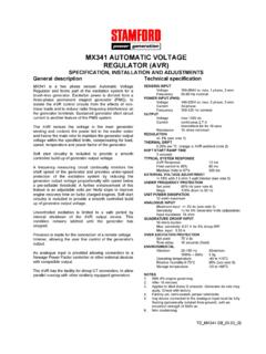
8 L-NVoltageFactorVoltageFactorx sustained current value is constant irrespectiveof voltage levelThree-phase Short Circuit Decrement Curve. No-load Excitation at Rated SpeedBased on star (wye) sustained durationAll other times are unchangedInstantaneousSustainedMinimumUC I274F50Hz60 HzSustained Short Circuit = 750 AmpsSustained Short Circuit = 920 AmpsNote 1 The following multiplication factors should beused to adjust the values from curve betweentime seconds and the minimum currentpoint in respect of nominal operating voltage :Note 2 The following multiplication factor should beused to convert thevalues calculated in accordance withNOTE 1 tothose applicableto the various types of short circuit :Note 3 Curves are drawn for Star(Wye)connected machines. For otherconnection the following multipliers should be applied to currentvalues as shown.
9 Parallel Star = Curve current value X 2 Series Delta = Curve current value X (secs)CURRENT (Amps) (secs)CURRENT (Amps)SYMMETRICALASYMMETRICAL7 Class - Temp RiseSeries Star (V) 3804004154403804004154403804004154403804 00415440 Parallel Star (V) 1902002082201902002082201902002082201902 00208220 Series Delta (V) 2202302402542202302402542202302402542202 30240254kVA (%) Input Star (V) 4164404604804164404604804164404604804164 40460480 Parallel Star (V) 2082202302402082202302402082202302402082 20230240 Series Delta (V) 2402542662772402542662772402542662772402 54266277kVA (%) Input 311 / Power F - 105/40 CCont.
10 H - 125/40 CStandby - 150/40 CStandby - 163/27 CDIMENSIONS PO Box 17 Barnack Road Stamford Lincolnshire PE9 2 NBTel: 00 44 (0)1780 484000 Fax: 00 44 (0)1780 484100 Website: 2002 Newage International with permission of in