Example: stock market
取扱説明書|UHFラインブースター UB18L : マスプロ電工
Voltage Standing Wave Ratio 入・出力インピーダンス Input/Output Impedance 電源 Power Requirements 使用温度範囲 Temperature Range 外観寸法 Dimensions 質量(重量) Weight 利得 Gain 雑音指数 Noise Figure マスプロの規格表に絶対うそはありません。保証します。 増幅部
Tags:
Information
Domain:
Source:
Link to this page:
Documents from same domain

CATV 屋外用 2分配 保安器 - maspro.co.jp
www.maspro.co.jpMASter of PROduction 生産の覇者 2K56-201 KW (B) ·89-5201 本社 〒470-0194(本社専用番号)愛知県日進市浅田町上納80 -2L ...

品名 型式 部品明細表 番号 部品名 材質 表面処理 1
www.maspro.co.jp図番 KE- 10 47 F型コネクター 黄銅 VU/BS・CS分波器(セパレーター) CSR7DW カバー ABS F型端子 品名

UHF・BS・CSブースター - maspro.co.jp
www.maspro.co.jp必ずお読みください 安全上のご注意 困ったときは uhfの入力レベル調整スイッチを「0db」にし,uhfの利得 調整を 右 へゆっくり回してください。 それでも画像が改善されないときは,uhfア …

UHF BS CS BOOSTERS UHF ch.13 BS UBCBW35 板壁 …
www.maspro.co.jp屋外(内)用uhf・bs・csブースター(増幅部) 取扱説明書 f型端子 uhf・bs・cs boosters 増幅チャンネル uhf ch.13~52・bs・110˚cs ubcbw35 35db型 ubcbw41 41db型 スカパー! 対応 3224mhz対応 取付方法 各部の名称と機能
www.maspro.co.jp
www.maspro.co.jpAASPRO WHC7M-C(flF ) Jñf HD 61 .5rn—-oo ffftÍÓ10m 2.4GHz G7-SK (FHSS) 4Mbps MPEG-4 n*300m (HMbfrã*) * 63.2m el DC9V (ACT'5î3—fffi :ACI OOV

CATV・VU・BS・CS デジタル レベル ... - …
www.maspro.co.jp1 catv・vu・bs・cs デジタル レベルチェッカー デジタル放送対応 2600mhz対応 取扱説明書 lcn3 catv·vu·bs·cs digital level checker 測定周波数 70~770mhz,950~2600mhz
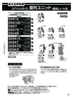
CATV VU BS CS 直列ユニット 壁面 ... - maspro.co.jp
www.maspro.co.jpdsk10 catv•vu•bs•cs 直列ユニット壁面埋込・シールド型 wall outlets 伝送周波数帯域 10~2655mhz 1端子型 2端子型 dskt dsk8r 2dsk15 2dskt 2dsktd dskt

CATV・VU・BS・CS デジタル レベル ... - maspro.co.jp
www.maspro.co.jp1 マスプロ catv ・ vu ・ bs ・ cs デジタルレベルチェッカー lcv3 catv・vu・bs・cs デジタル レベルチェッカー 映像・音声確認機能付 取扱説明書 lcv3 保証書付 catv·vu·bs·cs digital …

デジタルレベルチェッカー - maspro.co.jp
www.maspro.co.jp2 安全上のご注意 ご使用の前に、この「安全上のご注意」をよくお読みください。 絵表示について 絵表示の例
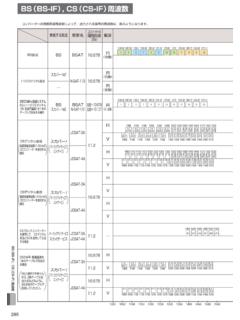
BS(BS-IF), CS(CS-IF)周波数 - maspro.co.jp
www.maspro.co.jpbs(bs-if), cs(cs-if)周波数 1049.48 1 1087.84 3 1126.2 5 1164.56 7 1202.92 9 1241.28 11 1000 1050 1100 1150 1200 1250 1300 1350 1400 1450 1500 1550
Related documents

RF Engineering Basic Concepts: The Smith Chart - Indico
indico.cern.chspacing and the ratio of maximum to minimum voltage reading. This is the origin of the VSWR (voltage standing wave ratio) which we will discuss later again in more detail . Movable electric field probe. DUT or . terminating . impedance. from generator. RF Basic Concepts, Caspers, McIntosh, Kroyer 5.

ENGINEERING PHYSICS I & II
www.tndte.gov.inWave motion–Introduction and definition–Audiable range-Infrasonic-Ultrasonics-Progressive waves, longitudinal and transverse waves–Examples- Amplitude, wave length, period and frequency of a wave–Definitions-Relation between wave length, frequency and velocity of a wave-Stationary or standing waves. Vibrations-Free
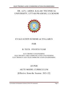
EVALUATION S CHEME & SYLLABUS FOR B. TECH. FOURTH …
aktu.ac.inand transmission coefficient, standing wave, standing wave ratio, line impedance and admittance, Introduction to strip lines, Microstrip Transmission line (TL). Wave Guide: Rectangular Wave guide -Field Components and Parameters, TE, TM Modes, Dominant Mode, Circular Waveguides: TE, TM modes. Wave Velocities, Wave guide Cavities. 10

Study Unit Understanding and Using Electronic Diagrams
www.workforcedevelopment.comvoltage of 120 volts, so the step-down transformer in Figure 1 has a turns ratio of 120 V/18 V = 6.67:1. Since the second-ary voltage is 18 volts and the maximum current is 2 amps, you know that the maximum volt-amp (VA) rating of the transformer is 18 V 2 A = 36 VA. A replacement trans-former would need to have the same secondary voltage, but

KENWOOD
www.kenwood.comtem which shows a standing wave ratio of less than 1.5 : 1 when using 50 ohm coaxial transmission liner or a system that results in a transmission line input impedance that is essentially resistive, and between 20 and 1 50 ohms will take power from the transceiver through the AT-940. If open wire or balanced type transmission line is used with

No Nonsense Technician Class - KB6NU's Ham Radio Blog
www.kb6nu.comUnits and terms: current, voltage, and resistance; alternating and direct current; conductors and insulators Figure 1 shows a simple electric circuit. It consists of a voltage source (in this case a battery, labeled x), a resistor (labeled R), and some wires to connect the battery to the resistor. When connected in this