Transcription of Understanding Electric Motor Nameplates
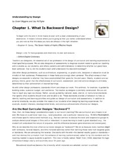
1 Electrical Tech Note 103 Agricultural Engineering DepartmentMichigan State University Understanding Electric Motor Nameplates1 Understanding the information provided on an Electric Motor nameplate and how to use theinformation is important. It may be necessary to replace an Electric Motor in the future, andnameplate information in needed to make sure the replacement Motor is acceptable for theapplication. Nameplate information is provided in manufacturers catalogs, and selecting theright Motor for an application requires an Understanding of that information. The followingdiscussion explains information found on a typical Motor nameplate, and how that informationcan be used. Figure 1 shows a typical Motor nameplate. Some Motor Nameplates provideadditional information. Figure 1 Nameplate of a typical dual-voltage, 3-phase, squirrel cage The frame number is necessary to know when replacing a Motor , or ordering a motorfor an application.
2 The frame number will specify the mounting dimensions for the Motor , shaftdiameter, and shaft height. If the frame numbers of two different motors are identical, themounting dimensions and shaft diameter will be the same even if the motors are made bydifferent manufacturers. An industry trade organization, NEMA, National ElectricalManufacturers Association, sets and maintains electrical industry manufacturing specifications1 Developed by Truman C. Surbrook, , , Master Electrician and Professor, and Jonathan R. Althouse, MasterElectrician and Instructor, Agricultural Engineering Department, Michigan State University, East Lansing, MI 48824-1323. For acopy of this Tech Note and other educational papers, visit the Electrical Technology web site at MSU is an affirmative-action, equal-opportunity institutionCopyright 2016, Biosystems & Agricultural Engineering Department, Michigan State University.
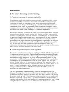
3 All rights reserved Electrical Tech Note 103 Page 2such as Motor frame numbers. A manufacturer may add letters to the frame number to specifyoptions available from that manufacturer. There are specific numbers and letters which havethe same meaning regardless of which manufacturer builds the Motor . There are motors builtfor specific purposes that have unique frame numbers. This discussion deals with generalpurpose motors. The frame number specifies dimensions of a general purpose Motor frame. Figure 2 is aview of the underside of an Electric Motor . The letters are NEMA standard letters and theactual dimensions for general purpose motors are shown in Table 1. The diameter of the bolthole of the Motor mounting bracket is letter H. The diameter is 1/32 of an in. larger than thebolt used for mounting. For example in Table 1, the bolt hole for a Motor frame 143T is 13/32in.
4 The proper bolt for mounting this Motor is 12/32 in. or d in. The dimension F is not veryuseful by itself, therefore, usually the dimension is given as 2F. The dimension 2F is thedistance from the center of one bolt hole to the center of the other bolt hole measured parallelto the shaft. The dimension E is the distance from the center of the bolt hole to the center lineof the shaft. If the distance from the center of one bolt hole to the center of the other measuredperpendicular to the shaft is desired, then that distance is two times E or 2E. The dimension BA is the distance from the center of the bolt hole nearest the shaft end ofthe Motor to the point where the shaft is exposed. This distance is used in combination with theexposed shaft length V to determine if the Motor gear or pulley will line up with the machinegear or pulley.
5 The actual shaft diameter may be listed as shaft diameter, or it may be given asthe dimension U. In Table 1, there is a column labeled shaft diameter. Figure 2 This is a bottom view of an Electric Motor showing the mounting bracket andstandard letters used to specify the frame number is followed by the letter C, the Motor is face mounted. That meansthat the bolt holes are on the shaft end of the Motor . Motors which are mounted as shown inFigure 2 usually have only a frame number or a frame number followed by the letter T or theletter U. These are often referred to as T-frame motors and U-frame motors. There are somedifferences in dimensions even though the numbers are the same as shown in Table 1. AU-frame is heavier and more massive than a T-frame of the same number. For example,compare the weight of the Motor with the 254T frame in Table 3 with the Motor with the 254 Uframe in Table 4.
6 Figure 3 shows a side view of an Electric Motor . Some of the dimensions shown in Figure2 are also shown in Figure 3. Dimension D is the distance from the bottom of the mountingCopyright 2016, Biosystems & Agricultural Engineering Department, Michigan State University. All rights reserved Electrical Tech Note 103 Page 3bracket to the center of the shaft. If an Electric Motor is to be directly coupled to a machineshaft, this dimension is very important. Figure 3 Side view of an Electric Motor showing the standard mounting dimensionletters. Table 1 Motor frame numbers and mounting dimensions for Electric Shaft KeyBA D E 2F H V No. dimensions in inches 42 d 3/64 3/642-1/162e1 1-11/16 9/32 slot1c 48 3/64 3/642 32c2 11/32 slot1 56 e 3/16 3/162 3 2-7/16311/32 slot1f143T f 3/16 3/162 3 2 413/322 145T f 3/16 3/162 3 2 513/322 182 f 3/16 3/162 4 3 4 13/322182T 1c 1/4 1/42 4 3 4 13/322 184 f 3/16 3/162 4 3 5 13/322184T 1c 1/4 1/42 4 3 5 13/322 213 1c 1/4 1/43 5 4 5 13/322 213T 1d5/16 5/163 5 4 5 13/323c215 1c 1/4 1/43 5 4 713/322 215T 1d5/16 5/163 5 4 713/323c254U 1d5/16 5/163 6 58 17/323 254T 1e 3/8 3/84 6 58 17/323 256U 1d5/16 5/164 6 51017/323 256T 1e 3/8 3/84 6 51017/323 284U 1e 3/8 3/84 75 9 17/324e284T 1f 1/2 1/24 75 9 17/324d286U 1e 3/8 3/84 75 1117/324e286T 1f 1/2 1/24 75
7 1117/324d324U 1f1/2 1/25 86 10 21/325d324T 2c1/2 1/25 86 10 21/325 Copyright 2016, Biosystems & Agricultural Engineering Department, Michigan State University. All rights reserved Electrical Tech Note 103 Page 4A key is used to prevent a gear or pulley from turning on the Motor shaft. The size of thekey slot is determined by the frame number. This is illustrated in Figure 4. The key dimensionmay be given as shown in Table 1. Some manufacturers actually specify the size of thekeyway or slot in the Motor shaft. The first dimension will be the width of the keyway which isthe dimension of the key needed. For example, the keyway dimension may be shown as 3/16 3/32. This means that the key way is 3/16 in. wide which requires a key that is 3/16 in. square. The second number 3/32 is simply the depth of the keyway in the Motor shaft.
8 The keywaymaximum length may also be given. Usually length is not important because a key is cut to thedesired length. The most important number is the width of the keyway (the first number) orsimply the key 4 A square cross-section key cut to length is usually used to prevent a gear orpulley from turning on the Motor It is important to match the horsepower when replacing an Electric Motor , butthere is more to replacing a Motor than simply matching the horsepower. A Motor should bereplaced with one of the same type. This may require the help of a person experienced inworking with motors. For example, a single-phase capacitor-start induction-run Motor shouldbe replaced with the same type. A split-phase single-phase Motor may have the samehorsepower, frame size, and similar features, but it has a much lower starting torque than acapacitor-start Motor .
9 Information used by an expert to match motors is the design letter,service factor, code letter, and insulation class. These will be discussed later. Electric motorsshould be matched to the load as close as possible. Electric motors are designed for maximumefficiency when operating at or near rated horsepower. Efficiency usually drops rapidly whenan Electric Motor operates well under the rated horsepower on the nameplate. VOLTS Electric motors must be matched to the voltage of the circuit. Some motors are onlysingle voltage. If that is the case, then only one voltage will be shown on the nameplate. Manygeneral use motors are dual voltage. They can be connected to operate at two or morevoltages. Connecting a single-phase dual voltage Motor for operation at different voltages isdiscussed later. The Motor with the nameplate shown in Figure 1 is a dual voltage Motor .
10 Theslash (/) is very important. It separates the two different voltages. A typical single-phase dualvoltage Motor would operate at 115 volts or at 230 volts. Commercial buildings often havesingle-phase power available at 115 volts and at 208 volts. The 208 may seem like a strangevoltage but it is very common. The Motor with the nameplate of Figure 1 shows the leadconnections for operation at 240 volts (low voltage) and at 480 volts (high voltage). Electric motors are rated for operation at such voltages as 115 and 230. These areconsidered nominal voltages for motors. Usually the circuit will have a voltage greater than 115volts or greater than 230 volts. Actual circuit voltages may be as high as 125 and 250. Havinga circuit voltage a little higher than the Motor voltage is usually not a problem. There are somemotor and circuit voltage combinations which should be avoided.