Transcription of Understanding Fan System Effects - Greenheck Fan
1 A technical bulletin for engineers, contractors and students in the air movement and control Box 410 Schofield, WI 54476 Fax 2017 Greenheck Fan Application FA/101-99 Fan Application FA/101-99 Greenheck Product Application Guide Greenheck Product Application GuideIt is important to realize that fan manufacturers can only guarantee the fan to perform as tested. The following examples will show manufacturer test conditions compared to installation with obstructions, such as elbows, guards or dampers, directly at the fan inlet or outlet. These obstructions cause additional losses that are not included in the fan manufacturer s tests, and in many cases, are not included in the designers usual System resistance calculations.
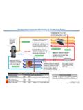
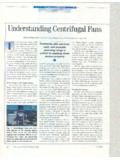
2 Most designers are well trained in determining the resistance that occurs in the System s ducts, filters, dampers and elbows that are located some distance from the fan, but they pay little attention to obstructions near the fan. The interaction of the air and the obstruction just prior to the fan causes the additional losses known as System following figures illustrate how fans are tested in comparison to how they are sometimes installed. Roof Exhaust FansFigure 1 illustrates how roof exhausters are tested. Additional vertical straight duct would have little if any effect.
3 Figures 2 and 3 illustrate roof exhaust fan installations having System Effects . Figure 3 illustrates the worst case, because the damper is located in a turbulent airstream. To improve on installations where horizontal ducts are used directly under the roof line, turning vanes should be installed in the elbows. In addition, a higher curb or extended base should be used. Higher curbs result in the elbow being further from the damper and fan inlet. The air moving industry uses a common term to describe certain inlet and outlet conditions that adversely affect fan performance.
4 The term used is System effect . Perhaps the term should be fan installation effect , because System effect results from the difference in how the fan was tested, compared to how it is installed. To minimize System Effects , air must enter or leave a fan let s take a look at how fans are tested and cataloged. Most fans available in today s market bear AMCA Certified Rating Seals. This means that the fan manufacturer followed the test procedures as outlined in AMCA Publication 210 and tested the fan in one of the standardized configurations approved by AMCA. One of the requirements of AMCA, is that directly under the cataloged performance for a given fan model, the fan manufacturer must make a statement as to how that product was tested.
5 Paying attention to these statements is the first step in avoiding System effect statements for three different product types are:Roof exhaust fans: Performance shown is for Installation Type A: Free inlet, Free outlet. Power rating (BHP) does not include drive losses. Performance ratings do not include the Effects of appurtenances in the axial fans: Performance shown is for Installation Type B: Free inlet, ducted outlet. Power rating (BHP) does not include drive losses. Performance ratings do not include the Effects of appurtenances in the fans: Performance shown is for Installation Type B: Free inlet, ducted outlet.
6 Power rating (BHP) does not include drive losses. Performance ratings do not include the Effects of appurtenances in the airstream. Understanding Fan System EffectsFig. 1 Fig. 2 Fig. 3 Figure 1 is typical of how roof exhausters are tested. AMCA Publication refers to this set up as Type A: Free inlet, free outlet. Fig. 1 GoodIt s understandable that in many cases an installation will end up having obstruction at the inlet or outlet (or both) causing System effect. If these situations cannot be avoided at the design stage, the System effect should be estimated and added to the calculated System resistance.
7 Keep in mind that the standard procedures for the design of duct systems are all based on the assumptions of uniform flow profiles in the System . The standard adds for resistance of elbows does not account for the loss when the elbow is close to the fan. AMCA has recognized this problem and has published guidelines on how to compensate for System Effects in its Publication 201, Fans and Systems . The designers who fully understand System Effects , and design to avoid them, must also follow-up with the installers to make sure the installation is as are the penalties of System effect?
8 Even when we recognize causes of System effect and we compensate for their losses, penalties result. The penalty starts with fans selected at higher speeds to compensate for additional losses. Higher speeds result in larger motors, increased cost, reduced efficiencies, increased vibration, and acoustical Effects . Acoustical Effects are usually completely overlooked even though the acoustic System effect penalty might be quite severe. The severity depends on how inadequate the fan to System connection is. In any case, you cannot expect the fan sound ratings to be as cataloged if System effect shooting existing installations when the System is short of air and pressure due to overlooked System Effects or poor installation practices can be quite interesting.
9 In most of these cases, it s very difficult to take accurate performance readings because of obstruction and turbulence at the fan inlet or now the finger pointing starts. Is it the fan or is it a System problem? So the big question arises, is the fan installed exactly as tested? In most cases, a visual inspection of the installation will lead you to a clear solve deficient fan System performance problems, it helps to have a clear Understanding of fan and System curves plus a knowledge of how to apply the fan 13 uses fan and System curves to illustrate the original design point, the deficient performance reading.
10 And the new fan and System curve with System 1 illustrates the original design 2 is the design volume on the corrected System 3 is where the deficient volume falls on the original System 4 is where the deficient volume falls on the corrected System curve.(All of the above is based on the assumption that the air density and the fan s speed are as designed)To further explain, let s consider an example where the System is delivering 20% less air than design (point 1). The deficient volume is point 3 as shown on the original System curve. The original curve calculation did not include allowance for System effect.