Transcription of Understanding Mobile Wireless Backhaul - fujitsu.com
1 Understanding Mobile Wireless Backhaul 1 Understanding Mobile Wireless Backhaull Understanding Mobile Wireless Backhaul 2 Introduction Wireless networks are evolving from voice-only traffic to networks supporting both voice and high-speed data services. As this transition occurs, there will be an increasing need for additional bandwidth at cell sites. Wireless service providers have very specific transport requirements and specifications for their services; Understanding these requirements is key to choosing the right technology and type of network for the application. The Wireless industry Backhaul transport requirements are defined by three primary factors: 1) Wireless 2G/3G standards 2) Cell site capacity requirements 3) Performance metrics (latency, jitter , availability).
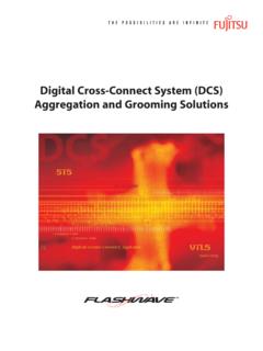
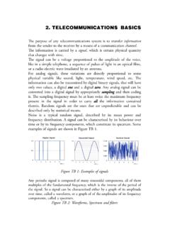
2 A thorough Understanding of these factors ensures operators choose the right technology, network and architecture to implement a successful Wireless Backhaul business strategy. Typical 2 GSM Network Overview In a typical GSM Wireless network, as shown in Figure 1, base station transceivers (BTS) are located at the cell site and provide the control and radio air interface for each cell. Base station controllers (BSC) provide control over multiple cell sites and multiple base station transceivers. The base station controllers can be located in a separate office or co-located at the Mobile switching center (MSC). Figure 1: Typical GSM Network Understanding Mobile Wireless Backhaul 3 The Wireless industry developed standard interfaces for interconnecting these devices, so they could deploy interoperable systems from multiple vendors.
3 The Abis interface connects the base station transceivers to base station controllers. The A interface in Figure 1 connects the base station controller to the Mobile switching center. A basic Understanding of these interfaces is important because the industry standards also specify the physical layer 1 interfaces. These physical interfaces define the Wireless Backhaul transport services and requirements. As data services were added to GSM cell sites, new elements were introduced into the network. An EDGE (Enhanced Data rate for GSM Evolution) blade is typically installed in the base station transceiver node to support data services up to 400 Kb/s. The EDGE blade communicates over the Gb interface, as shown in Figure 1, to the Serving GPRS/EDGE Support Node (SGSN) located in the Mobile switch center.
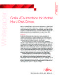
4 Voice services continue over the A interface, while data services are handled over the Gb interface. Similarly, 3G networks have their own set of defined interfaces between their base stations, (Node B), radio network controllers (RNC) and voice and data switches, as shown in Figure 2. Figure 2: Wireless Interface Requirements These Abis, A, Gb and Iu interfaces have historically defined Backhaul transport requirements, since they specify the physical layer 1 implementation. The Wireless industry s heavy reliance on T1 transport services is defined by and required by their industry specifications. While 3G/UMTS specifications have recently added native Ethernet interface support, 3G/UMTS equipment that supports native Ethernet interfaces is not expected to be available until early 2008.
5 TS / TDM DS1 to OC-12Iu-b, Iu-cs, Iu-psUMTSTS -T1/E1 GbTS -T1/E1 ATS -T1/E1 AbisGSMS tandardPhysical Layer SpecInterfaceTechnologyTS / TDM DS1 to OC-12Iu-b, Iu-cs, Iu-psUMTSTS -T1/E1 GbTS -T1/E1 ATS -T1/E1 AbisGSMS tandardPhysical Layer SpecInterfaceTechnology Understanding Mobile Wireless Backhaul 4 Understanding Wireless Capacity Requirements Given the Wireless industry s historical reliance on T1 circuits, the next issue in Understanding Wireless Backhaul is the actual capacity required at cell sites (# T1s). There has been a great deal of hype in the industry about the need for 100 Mb/s broadband services to every cell tower, however the reality is far more limited. Today, most cell towers are serviced by one to four T1s, equivalent to Mb/s to 6 Mb/s.
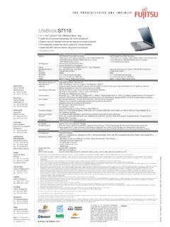
6 The addition of and 3G data services will increase the need for more bandwidth to cell sites, but the requirements are still relatively modest. The amount of bandwidth on a Wireless network is ultimately constrained by two factors: the amount of spectrum available and the spectral efficiency of the Wireless interface. Wireless frequencies, or spectrum, is allocated and auctioned by the FCC, typically in 10 or 20 MHz blocks. Half of each block is used for transmitting signal and the other half for receiving (FDD). Blocks are further subdivided into channels that are shared across cell areas. To avoid interference, adjacent cells use different sets of frequency channels, typically in a 1:4 or 1:7 pattern, as shown in Figure 3.
7 Spectral efficiency is the amount of data (bits/s) that can be transmitted for every Hz of spectrum. Newer technologies, such as EDGE and UMTS/HSDPA use advanced modulation schemes that allow higher data rates. The modulation schemes dynamically adjust to the channel conditions between the base station and handset (power, noise, interference and so on). The maximum amount of bandwidth required at a cell site is simply the amount of spectrum available multiplied by the spectral efficiency of the Wireless interface. For example, the table below illustrates the cell site bandwidth required for three scenarios, each with a different spectrum allocation: GSM 2G voice MHz GSM/EDGE MHz UMTS/HSPDA 3G MHz The results show that current 2G and EDGE networks are easily serviced by one to four T1s worth of bandwidth.
8 Even 3G cell sites, with three sector antennas and base stations, only require Mb/s of bandwidth or approximately 12 16 T1s. While bandwidth requirements are increasing, they are far less than 100 Mb/s per cell site. Another factor that determines the amount of bandwidth required at cell sites are the handsets themselves, a factor not included in the study shown above. Currently, only 15% of US handsets Fig 3 1:4 reuse pattern Understanding Mobile Wireless Backhaul 5 are 3G capable1. Even the widely popular Apple iPhone operates over the EDGE network (384 Kb/s) rather than the faster, more advanced 3G (HSDPA) network. Bandwidth requirements will remain modest until there is a wider adoption and deployment of 3G handsets, smart phones and Mobile PC cards, which in turn drive the need for higher capacities and throughputs at cell sites.
9 Historical Reliance on TDM Based on industry specifications and capacity requirements, it is very easy to understand why Wireless service providers have historically relied on T1 circuits for cell site transport. Given the heavy reliance on TDM services in the Wireless industry, it is worth investigating the options for fiber optic transport of these circuits. There are several methods of transporting TDM services in their native format (SONET, CWDM, DWDM) or by converting the TDM service to Ethernet (Circuit Emulation Service, known as CES). Due to a number of performance factors, many Wireless service providers continue to rely on and require TDM services carried over a native TDM transport infrastructure.
10 It is important to understand these performance issues when selecting the appropriate transport technology for their Wireless Backhaul networks. Latency, jitter and Availability: They Still Matter T1s have historically been utilized for providing connections to cell sites. T1s are specified in the Wireless industry standards, they are a widely available service and T1 prices have declined from $1500 to $300 per month over the last ten years. The reduction in T1 prices has reduced or eliminated the disparity with Ethernet services. With the advent of Ethernet and IP data networks that support T1 circuit emulation (CES), the question becomes whether these packet-based networks can offer the same performance levels as their TDM counterparts and whether these networks meet the expectations of Wireless service providers.