Transcription of Understanding SIS Field Device Fault Tolerance …
1 2016 aeSolutions Paul GruhnSIS Field Device Fault Tolerance RequirementsMarch 6, 2016 Page 1 Understanding SIS Field Device Fault Tolerance requirements Paul Gruhn, , CFSE Global Functional Safety Consultant aeSolutions Abstract The IEC 61511 standard includes a table listing the Fault Tolerance requirements for Field devices for different safety integrity levels. There are clauses stating how the Fault Tolerance requirements may need to be increased in some cases, may be decreased in some cases, and alternative Fault Tolerance tables from IEC 61508 may be used in some cases. This paper will summarize all these requirements , as well as changes in the table that will appear in the second edition of IEC 61511 that is expected to be released in the summer of 2016.
2 Basic requirements The table from the standard showing the minimum hardware Fault Tolerance of sensors and final elements is reproduced here as Table 1. SIL Minimum Hardware Fault Tolerance 1 0 2 1 3 2 4 Special requirements apply (see IEC 61508) Table 1: Field Device Fault Tolerance Table from IEC 61511 A hardware Fault Tolerance of X means that X + 1 dangerous failures would cause a loss of the safety function. Another way to phrase it would be that a hardware Fault Tolerance of X means that the function could survive X dangerous failures. Table 2 is a listing of various configurations and their Fault Tolerance numbers. For MooN voting, the Fault Tolerance is simply N M. 2016 aeSolutions Paul GruhnSIS Field Device Fault Tolerance RequirementsMarch 6, 2016 Page 2 Fault Tolerance Configurations 0 1oo1, 2oo2 1 1oo2, 2oo3 2 1oo3, 2oo4 Table 2: Configurations and Their Fault Tolerance Numbers The tables mean that non Fault tolerant Field Device designs will meet SIL 1 requirements .
3 SIL 2 or higher will require Fault tolerant designs. One end user company has documented that each jump in SIL beyond SIL 1 represent an increase in cost of approximately $50,000 per function; that s how much the total installed cost of the extra Field devices will be. Note that Fault Tolerance is not synonymous with redundant . Redundant simply means more than one. 2oo2 is redundant, yet not Fault tolerant (of dangerous failures). A calculation example Using standard equations that have been published in a variety of sources for decades, and MTTFd (dangerous mean time to failure) figures published in the ISA 84 technical report on system modeling (that came from five end user companies), the Fault Tolerance table can be shown to be reasonable.
4 For example, using a pressure switch with a MTTFd of 40 years, a valve assembly with a MTTFd of 50 years, a logic solver certified for use in SIL 3, and yearly testing of the Field devices , the overall Risk Reduction Factor for the function would be 44. SIL 1 represents a Risk Reduction Factor between 10 and 100. Cases where Fault Tolerance must be increased Clause states that if the dominant failure mode is not to the safe state, or if dangerous failures are not detected, then the Fault Tolerance requirements need to be increased by one. An example of such a case would be an energize to trip function that does not utilize line monitoring to reveal open circuits in wiring. Normally de energized devices are not inherently fail safe. Fault tolerant designs for SIL 1 are obviously not financially attractive.
5 Cases where Fault Tolerance may be decreased Clause states that the Fault Tolerance requirements can be reduced by one if certain conditions apply, primarily that the devices are selected on the basis of prior use. This means that the user can document that the failure rates of the Field devices are low enough to meet SIL 2 in a 1oo1 configuration. This is not easy for most end users to do, as described below. 2016 aeSolutions Paul GruhnSIS Field Device Fault Tolerance RequirementsMarch 6, 2016 Page 3 Prior use Clause covers prior use. This means that appropriate evidence shall be available that devices are suitable for use. The evidence of suitability shall include the following: consideration of the manufacturer s quality, management and configuration management systems adequate identification and specification of the components or subsystems demonstration of the performance of the components or subsystems in similar operating profiles and physical environments the volume of operating experience.
6 A note in clause mentions having a confidence limit of 70% of the failure rate data. Another calculation example As an example, consider the function analyzed earlier, but this time assuming a pressure switch with a MTTFd of 200 years, and a valve with a MTTFd of 150 years. (Please realize that such numbers are significantly optimistic compared to published sources of process industry maintenance data.) The resulting Risk Reduction Factor for the function would now be 170. SIL 2 represents a Risk Reduction Factor between 100 and 1,000. Cases where alternative Fault Tolerance tables may be used Clause states that alternative Fault Tolerance tables may be used providing an assessment is made according to the requirements of IEC 61508. Those tables are reproduced here as Tables 3 & 4.
7 Safe Failure Fraction Hardware Fault Tolerance 0 1 2 < 60% SIL 1 SIL 2 SIL 3 60% < 90% SIL 2 SIL 3 SIL 4 90% < 99% SIL 3 SIL 4 SIL 4 99% SIL 3 SIL 4 SIL 4 Table 3: Architectural constraints for type A subsystems 2016 aeSolutions Paul GruhnSIS Field Device Fault Tolerance RequirementsMarch 6, 2016 Page 4 Safe Failure Fraction Hardware Fault Tolerance 0 1 2 < 60% Not allowed SIL 1 SIL 2 60% < 90% SIL 1 SIL 2 SIL 3 90% < 99% SIL 2 SIL 3 SIL 4 99% SIL 3 SIL 4 SIL 4 Table 4: Architectural constraints for type B subsystems In order to use these two tables, one must understand what is meant by type A and B subsystems, and what is safe failure fraction. Type A devices are considered to be simple devices with known, predictable failure modes.
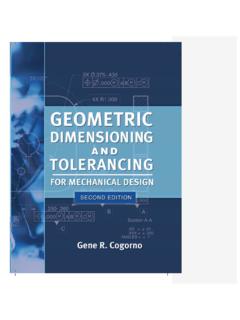
8 Type B devices are considered to be complex devices with unknown, unpredictable failure modes. Essentially, anything with a microprocessor is considered type B. PLCs and smart transmitters are considered type B devices . Safe failure fraction (SFF) Safe failure fraction is the ratio of safe failures, plus dangerous detected failures, divided by the total. Figure 1 can be used to explain the concept. Figure 1: Failure Categories The definition stated above can be written as SFF = ( SU+ SD+ DD) / Total. Lambda ( ) is the term used to represent failure rate in the world of reliability engineering. Assuming a standard transmitter with a MTTFs of 80 years, a MTTFd of 80 years, and 50% diagnostic coverage (all reasonable values), the safe failure fraction would be 75% (exactly as shown in Figure 1).
9 According to Table 4 above, a 1oo1 2016 aeSolutions Paul GruhnSIS Field Device Fault Tolerance RequirementsMarch 6, 2016 Page 5 transmitter would be suitable for use in SIL 1 only. So how is it that there are devices available that are certified for use in SIL 2 in a 1oo1 configuration? It s simple actually; their diagnostic coverage and safe failure fraction are much higher. If the same transmitter had a diagnostic coverage factor of 90%, its safe failure fraction would then be 95%, thus making it suitable for use in SIL 2. About the only method of getting a valve (a type A) Device to have a safe failure fraction in the 60 90% range (thus making it suitable for use in SIL 2), would be to implement automated partial stroking. While there are over a dozen vendors offering partial stroke solutions, many users have reported a lack of satisfaction with them.
10 (This should not, however, be taken as an overall condemnation of the concept of partial stroking.) Why is the IEC 61511 Fault Tolerance table not based on safe failure fraction? The Fault Tolerance table in IEC 61511 for programmable logic solvers is based on safe failure fraction, but the table for Field devices is not. Why is this? Simply put, when the table was being discussed and finalized around the year 2000, no one in industry really had any idea of what the safe failure fraction of most Field devices were. Only two vendors at that time had recently developed certified sensors, and it took most other Field Device vendors almost a decade to jump on the bandwagon and develop safety variants of their products. The committee obviously couldn t base a table on data that no one in industry had.