Transcription of Unique technology for 3D integrity monitoring of subsea
1 Tittelav NavnUnique technology for 3D integrity monitoring of subsea pipelinesWelland subsea IntegrityWorkshopOctober26, Rio de JaneiroTrond OlsenPresident, clampon , BUILT A FLOW RIG BUT THE PLUMBER WANTED 500 USD,..AND WE DID NOT HAVE THE 500!!!Non-Intrusive ultrasonic intelligent Sensors-Sand monitoring -PIG Detection-Leak monitoring -Vibration monitoring -Well Collision Detection-Wall Thickness monitoring -Corrosion-Erosion monitoring -Onshore, topside & subsea -Service / into todayThe Acoustic City BergenStatoilChristianMichelsenResearch( CMR)Bergen University College campusHaukeland University HospitalNew R&D park at MarineholmenUniversity ofBergenInstitute ofMarine ResearchCompanies:ClampOnAADI (Xylem)KTNH alfwaveNaxys(GE)FluentaAGR PipetechBTC ArcherXsensOctioKongsbergMaritimeCGG VeritasRoxar(Emerson)TracercoMETASCodaOc topusSimrad/SimtechSubseaWemaMajor local users of acoustic technologies and products.
2 Statoil, Schlumberger, Baker Hughes, Aker Solutions, FMC Technologies, OneSubsea, DOF subsea , Royal Norwegian Navy, HaukelandUniversity HospitalDifferencesRio de Janeiro -BergenSimilaritiesRio de Janeiro -BergenBergen wherewekeepthehead oftheBacalaoCEM ProductIf you have issues like this .. you could be facingAbkatun-A, Mexico corrodedgas lineYour challenge .. Difficult access assets Inaccessible sections of pipelines Unpiggablepipelines Estimation of corrosion/erosion rates for life management Avoid shutting down production to inspectFrom random inspectionto continuous monitoringParadigm shiftLicense to operate demonstratingsafe operationsCEM monitoring based on GWT w/tomographyNon-intrusive permanently installed corrosion/erosion monitoring technology providing a cost-efficient solutionWhat we bring to the table.
3 Conventional manual gaugeLimited spot coverageGuided wave transducer ringsFull volume coverageWhy guided waves Measures WT between the transducers in line of sight Resolution/sensitivity better then 1% of WT Signal is Robust and will not break down Transducers can be mounted on the outside of coating <1mm thickness Measures WT between the transducers in line of sight Resolution/sensitivity better then 1% of WT Signal is Robust and will not break down Transducers can be mounted on the outside of coating <1mm thicknessCEM Coverage Area w/GWT5 signal paths per transducer direct, clockwise and counter clockwise helical and 2 turn helical Max distance is 5 x OD -Min distance is 20 x WTCEM Proving the technologyDefect #1 Defect #12 Tomography Results w/EDMEDM = Electrical Discharge MachiningA copper electrode was machined to pipe surface shape and we eroded out in 12 different steps with increasing steps of 20um, 40um etc steps Circumferential position [mm]Axial position [mm]Maximum Corrosion Depth mm 0100200300400500600050100150200250300350 400450500 Wall Thickness Loss [%]01234567891011 Defect #1 Result 2D-viewCircumferential position [mm]Axial position [mm]Maximum Corrosion Depth mm 0100200300400500600050100150200250300350 400450500 Wall Thickness Loss [%]01234567891011 Defect #2 Result 2D-viewCircumferential position [mm]Axial position [mm]
4 Maximum Corrosion Depth mm 0100200300400500600050100150200250300350 400450500 Wall Thickness Loss [%]01234567891011 Defect #3 Result 2D-viewCircumferential position [mm]Axial position [mm]Maximum Corrosion Depth mm 0100200300400500600050100150200250300350 400450500 Wall Thickness Loss [%]01234567891011 Defect #4 Result 2D-viewCircumferential position [mm]Axial position [mm]Maximum Corrosion Depth mm 0100200300400500600050100150200250300350 400450500 Wall Thickness Loss [%]01234567891011 Defect #5 Result 2D-viewCircumferential position [mm]Axial position [mm]Maximum Corrosion Depth mm 0100200300400500600050100150200250300350 400450500 Wall Thickness Loss [%]01234567891011 Defect #7 Result 2D-viewCircumferential position [mm]Axial position [mm]Maximum Corrosion Depth mm 0100200300400500600050100150200250300350 400450500 Wall Thickness Loss [%]01234567891011 Defect #8 Result 2D-viewCircumferential position [mm]Axial position [mm]Maximum Corrosion Depth mm 0100200300400500600050100150200250300350 400450500 Wall Thickness Loss [%]01234567891011 Defect #9 Result 2D-viewCircumferential position [mm]Axial position [mm]Maximum Corrosion Depth mm 0100200300400500600050100150200250300350 400450500 Wall Thickness Loss [%]01234567891011 Defect #10 Result 2D-viewCircumferential position [mm]Axial position [mm]Maximum Corrosion Depth mm 0100200300400500600050100150200250300350 400450500 Wall Thickness Loss [%]01234567891011 Defect #11 Result 2D-viewCircumferential position [mm]Axial position [mm]
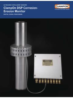
5 Maximum Corrosion Depth mm 0100200300400500600050100150200250300350 400450500 Wall Thickness Loss [%]01234567891011 Defect #12 Result 2D-viewComparison with coarse calliper measurements1234567891011120100200300400 5006007008009001000 Defect #Estimated max. depth (mm)CorrPrintManual gageLaser scan min point with Bend Tomography01234 Wall loss [% wt]Available ultimo 2015 topside and subseaSubsea CEM configurations-3 adifferentmodels -CEM for ROV installation-CEM under insulation/coating -CEM w/mechanical cover Pre Installed -Green field ROV Installed -Brown field Fully interfaced Internal data storage Battery or SCM poweredpowerConsumption Wireless CommunicationCEM provide Continousmonitoringfor lifeoffield High resolution3D tomographyofpipe condition Sensitivity1% ofwallthickness Lowpowerconsumption SCS or batterypower SCS communicationor localdata storage Non-intrusiveCEM Field examplesFPSO Skarv Norwegian SeaCorrosion-Erosion monitoringParticle monitoring Vibration monitoringTopsideCEM at BP Skarv FPSO sgard/Mikkel/Midgard CompressionSiakap-NorthMalaysiaSiakap-No rthPre-installed CEM The Corrosion-Erosion monitoring
6 SystemData Communication via Wave Glider SurfboardSystem in the field -SubseaBrownfield retrofit for GoM projectOnshore Application Examples Straight pipes Up to sixteen transducers mounted on two clamping bands over the selected area. Bends Up to sixteen transducers mounted on separate sides of a bend, monitoring the wall thickness loss in the bend. Reducers Up to sixteen transducers mounted on selected locations on the reducer. Uneven thickness profile is not a you for your attention!Any questions?Trond -+1-281-536-9363 President clampon .


