Transcription of UNIT 2 STEAM POWER PLANT Steam Power Plant - IGNOU
1 21 STEAM POWER PLANT UNIT 2 STEAM POWER PLANT Structure Introduction Objectives Basic Consideration in the Analysis of POWER Cycles STEAM Generator Super Heater Feed Water Heater Furnaces Energy Performance Assessment of Boilers STEAM Turbines Condenser Cooling Tower STEAM POWER Station Control Summary Key Words Answers to SAQs INTRODUCTION Two important area of application of thermodynamics are POWER generation and refrigeration . Both POWER generation and refrigeration are usually accomplished by a system that operates on a thermodynamics cycle .
2 Thermodynamics cycles can be divided into two generation categories : (a) POWER Cycles (b) refrigeration Cycles The devices or systems used to produce a net POWER output are often called engines and the thermodynamics cycles they operate on are called POWER cycle . The devices or systems use to produce refrigeration are called refrigerator, air conditioners or heat pumps and the cycles they operates on are called refrigeration cycles. Thermodynamic cycles can be categorized as : (a) POWER cycles or refrigeration cycles.
3 (b) Gas Cycles or Vapor Cycles : In gas cycles, the working fluid remains in the gaseous phase throughout the entire cycle , where as in vapor cycles the working fluid exists in the vapor phase during one part of the cycle and in the liquid phase during another part. (c) Closed Cycles or Open Cycles : In closed cycles, the working fluid is returned to the initial state at the end of the cycle and is re-circulated. In open cycle , the working fluid is renewed at the end of each cycle instead of being re-circulated.
4 22 POWER PLANT Engineering Objectives After studying this unit, you should be able to know STEAM generator, STEAM turbine, and describe cooling towers and condensers. BASIC CONSIDERATION IN THE ANALYSIS OF POWER CYCLES Actual cycle The cycles encountered in actual devices are difficult to analyze because of the presence of complicating effects, such as friction and the absence of sufficient time for establishment of the equilibrium conditions during the cycle . Ideal cycle When the actual cycle is stripped of all the internal irreversibilities and complexities, we end up with a cycle that resembles the actual cycle closely but is made up totally of internally reversible processes.
5 Such a cycle is called an Ideal cycle . Heat Engines Heat engines are designed for the purpose of converting other form of energy to work and their performance is expressed as thermal efficiency. netthin WQ The Idealization and Simplification (a) The cycle does not involve any friction. (b) All expansion and compression process take place in a quasi-equilibrium manner. (c) The pipe connecting the various component of a system are well insulated and heat transfer and pressure drop through them are negligible.
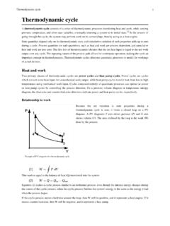
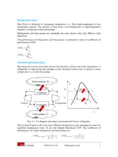
6 Carnot cycle The Carnot cycle is composed of 4 totally reversible processes : (a) Isothermal heat addition at high temperature (TH). (b) Isentropic expansion from high temperature to low temperature. (c) Isothermal heat rejection at low temperature (TL). (d) Isentropic compression from low temperature to high temperature. Thermal efficiency of Carnot cycle = th, carnot1 LHTT The Carnot Vapor cycle (a) A steady-flow Carnot cycle executed with the saturation dome of a pure substance is shown in Figures (a) and (b).
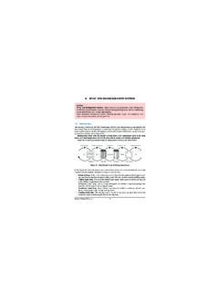
7 The fluid is heated reversibly and isothermally in a boiler (process 1-2), expanded isentropically in a turbine (process 2-3), condensed reversibly and isothermally in a condenser (process 3-4) and compressed isentropically by a compressor to the initial state (process 4-1). 23 STEAM POWER PLANT (b) The Carnot cycle is not a suitable model for vapor POWER cycle because it cannot be approximated in practice. (a) (b) Figure : Carnot cycle Rankine cycle : The Ideal cycle for Vapor POWER cycle (a) The impracticalities associated with Carnot cycle can be eliminated by superheating the STEAM in the boiler and condensing it completely in the condenser.
8 This cycle that results is the Rankine cycle , which is the ideal cycle for vapor POWER plants. The construct of POWER PLANT and T-s diagram is shown in Figures (a) and (b). (a) (b) Figure : Rankine cycle 1 4 3 2 T s 4 3 2 1 T s Boiler Turbine Condenser qout Wturb,out wpump,in qin Pump 1 2 3 4 3 4 1 2 T s wpunp,in Wturb,out qin qout 24 POWER PLANT Engineering (b) The ideal Rankine cycle dose not involve any internal irreversibilities (c) The Rankine cycle consists of the following four processes : 1-2 : Isentropic compression in pump (compressors) 2-3 : Constant pressure heat addition in boiler 3-4 : Isentropic expansion in turbine 4-1.
9 Constant pressure heat rejection in a condenser Process 1-2 Water enters the pump at state 1 as saturated liquid and is compressed isentropically to the operating pressure of the boiler. The water temperature increases somewhat during this isentropic compression process due to slight decrease in the specific volume of the water. The vertical distance between state 1 and 2 on the T-s diagram is greatly exaggerated for clarity. Process 2-3 Water enters the boiler as a compressed liquid at state 2 and leaves as a superheated vapor at state 3.
10 The boiler is basically a large heat exchanger where the heat originating from combustion gases, is transferred to the water essentially at constant pressure. The boiler together with the section where the STEAM is superheated (the superheater), is often called the STEAM generator. Process 3-4 The superheated vapor at state 3 enters the turbine, where it expands isentropically and produces work by rotating the shaft connected to an electric generator. The pressure and the temperature of the STEAM drops during this process to the values at state 4, where STEAM enters the condenser Process 4-1 At this state, the STEAM is usually a saturated liquid-vapor mixture with a high quality.