Transcription of THERMODYNAMICS TUTORIAL 5 HEAT PUMPS AND …
1 THERMODYNAMICS TUTORIAL 5 heat PUMPS AND refrigeration On completion of this TUTORIAL you should be able to do the following. Discuss the merits of different refrigerants. Use thermodynamic tables for common refrigerants. Define a reversed heat engine. Define a refrigerator and heat pump. Define the coefficient of performance for a refrigerator and heat pump. Explain the vapour compression cycle . Explain modifications to the basic cycle . Sketch cycles on a pressure - enthalpy diagram. Sketch cycles on a temperature - entropy diagram. Solve problems involving isentropic efficiency. Explain the cycle of a reciprocating compressor. Define the volumetric efficiency of a reciprocating compressor. Solve problems involving reciprocating compressors in refrigeration . Explain the ammonia vapour absorption cycle . 1. INTRODUCTION It is possible to lower the temperature of a body by use of the thermo-electric affect (reversed thermo-couple or Peltier effect).
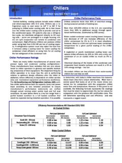
2 This has yet to be developed as a serious refrigeration method so refrigerators still rely on a fluid or refrigerant which is used in a reversed heat engine cycle as follows. Figure 1 heat is absorbed into a fluid (this is usually an evaporator) lowering the temperature of the surroundings. The fluid is then compressed and this raises the temperature and pressure. At the higher temperature the fluid is cooled to normal temperature (this is usually a condenser). The fluid then experiences a drop in pressure which makes it go cold (this is usually a throttle valve) and able to absorb heat at a cold temperature. The cycle is then repeated. Various fluids or refrigerants are used in the reversed thermodynamic cycle . Refrigerants such as air, water and carbon dioxide are used but most refrigerants are those designed for vapour compression cycles. These refrigerants will evaporate at cold temperatures and so the heat absorbed is in the form of latent energy.
3 Let's look at the properties of these and other refrigerants. 2 3 2. REFRIGERANTS Refrigerants are given R numbers. Carbon dioxide, for example is R744. Some of them are dangerous if released because they are either explosive or toxic. Toxic refrigerants are placed in categories. Sulphur dioxide, for example, is classed as toxic group 1 which means that death occurs after breathing it for 5 minutes. In the past the most popular fluids have been ammonia (R717),fluorocarbons and halo-carbons. The most popular of these is R12 or dichlorodifluoromethane (CF2Cl2). The type of refrigerant used in a cycle is largely governed by the evaporation temperature required and its latent capacity. Below is a list of some of them. Refrigerant R number Evaporation temp. Toxic group at bar.(oC) C Cl3 F R11 24 5 C Cl2F2 R12 -30 6 C ClF3 R13 -82 6 C F4 R14 -128 6 CH Cl2F R21 9 4 CH Cl F2 R22 -40 5 CH F3 R23 -84 5 C Cl2 F C Cl F2 R113 47 4 C Cl2 F C F3 R114A 3 6 C Cl2 F2 C Cl F2 R114 3 6 C
4 Cl2 F2 C F3 R115 -39 All the above are Halo-Carbons and Fluro-carbons which are non-flammable and may be detected by a halide torch or electric cell sensor. Other refrigerants are shown below. Ammonia is flammable and detected by going white in the presence of sulphur dioxide. It has a strong characteristic pungent smell. Death occurs when breathed for 30 minutes. NH3 R717 -33 2 Carbon Dioxide is safe and non-toxic but it can suffocate. CO2 R744 -78 Sulphur Dioxide is highly toxic and does not burn. Other refrigerants are in the Hydro-Carbon groups such as Propane, Butane and Ethane. These are explosive. Because of the problems with damage to the ozone layer, new refrigerants such as R134a have been developed and are now included in the thermodynamic tables. Now let's look at the use of thermodynamic tables for refrigerants.
5 4 3. TABLES The section of the fluid tables devoted to refrigerants is very concise and contains only two superheat temperatures. The layout of the tables is shown below. 15K 30 K t ps vg hf hg sf sg h s h s t is the actual temperature in degrees Celsius. ps is the saturation pressure corresponding to the temperature. It follows that if the refrigerant is wet or dry saturated, it must be at temperature t and pressure ps. If the refrigerant has 15 degrees of superheat, then the actual temperature is t+15 and the properties are found under the 15 K heading. Similarly if it has 30 K of superheat, its actual temperature is t+30. For example, R12 at bar and 20oC must have 30 K of superheat since its saturation temperature would is -10oC. From the 30 K columns we find that h= kJ/kg and s = kJ/kg K. When dealing with liquid refrigerant, take the properties as hf and sf at the given temperatures.
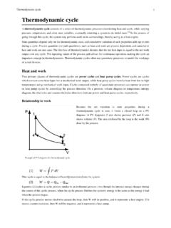
6 The pressures are never very high so the pressure term will not cause much error. 4. VAPOUR COMPRESSION CYCLES THE BASIC cycle refrigeration / heat pump cycles are similar to heat engine cycles but they work in reverse and are known as reversed heat engine cycles. A basic vapour cycle consists of isentropic compression, constant pressure cooling, isentropic expansion and constant pressure heating. You may recognise this as a reverse of the Rankine cycle or even the reverse of a Carnot cycle . The heating and cooling will involve evaporation and condensing. Let's consider the cycle first conducted entirely with wet vapour. Figure 2 The basic principle is that the wet vapour is compressed and becomes dryer and warmer in the process. It is then cooled and condensed into a wetter vapour at the higher pressure. The vapour is then expanded.
7 Because of the cooling, the expansion back to the original pressure produces a fluid which is much colder and wetter than it was before compression. The fluid is then able to absorb heat at the cold temperature becoming dryer in the process and is returned to the original state and compressed again. The net result is that heat is absorbed at a cold temperature and rejected at a higher temperature. Work is needed to drive the compressor but some of it is returned by the turbine. 5 The thermodynamic cycle for refrigerators is often shown on a pressure enthalpy diagram (p h) and professional charts are available but not used in the Engineering Council exams. Figure 3 shows the basic cycle . Figure 3 The four thermodynamic processes are 1 - 2 Isentropic compression.
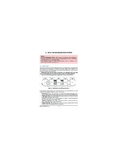
8 P(in) = mr(h2 - h1) 2 - 3 Constant pressure cooling. (out) = mr(h3 - h2) 3 - 4 Isentropic expansion. P(out) = mr(h3 - h4) 4 - 3 Constant pressure heating. (in) = mr(h4 - h1) mr = mass flow rate of refrigerant. In practice wet vapour is difficult to compress and expand so the refrigerant is usually dry before compression and superheated after. The cooling process may produce anything from wet vapour to under-cooled liquid. The expansion of a liquid in a turbine is impractical and so a throttle is used instead. 6 Figure 4 A throttle produces no useful work but it converts the pressure into internal energy. This makes the liquid evaporate and since the saturation temperature goes down it ends up cold. The enthalpy before and after a throttle are the same.
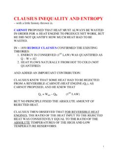
9 The entropy increases over a throttle. Figure 5 The cycle may also be drawn on a temperature entropy diagram as shown. The conditions shown are wet at (1), superheated at (2) and under-cooled at (3). These conditions vary. The four thermodynamic processes are 1 - 2 Isentropic compression. P(in) = mr(h2 - h1) 2 - 3 Constant pressure cooling. (out) = mr(h3 - h2) 3 - 4 Throttle (h3 = h4) 4 - 3 Constant pressure heating. Figure 6 (in) = mr(h4 - h1) COEFFICIENT OF PERFORMANCE The second law of THERMODYNAMICS tells us that no heat engine may be 100% efficient. In the reversed cycle , the reverse logic applies and it will be found that more energy is given out at the condenser and more absorbed in the evaporator, than is needed to drive the compressor. The ratio of heat transfer to work input is not called the efficiency, but the coefficient of performance or advantage.
10 There are two coefficients of performance for such a cycle , one for the refrigeration effect and one for the heat pump effect. REFRIGERATOR A refrigerator is a device for removing heat at a cold temperature so we are interested in the heat absorbed in the evaporator (in). The coefficient of performance is also called the advantage and is defined as = (in)/P(in) The heat absorbed is called the refrigeration affect. heat PUMP A heat pump is a device for producing heat so we are interested in the heat given out in the cooler (out). The coefficient of performance is defined as = (out)/P(in) It is usual to find a convenient source of low grade heat for the evaporator such as the atmosphere or a river. The heat is removed from this source and upgraded to higher temperature by the compressor. Both the work and the heat absorbed are given out at the higher temperature from the cooler. 7 5. MODEL REVERSED heat ENGINE Figure 7 The ideal model PUMPS heat from a cold source to a hot place.