Transcription of Unit 24: Applications of Pneumatics and Hydraulics
1 1 Unit 24: Applications of Pneumatics and Hydraulics Unit code: J/601/1496 QCF level: 4 Credit value: 15 OUTCOME 2 TUTORIAL 1 hydraulic pumps The material needed for outcome 2 is very extensive so there are ten tutorials in this outcome. You will also be completing the requirements for outcome 1 which is integrated into it. The series of tutorials provides an extensive overview of fluid power for students at all levels seeking a good knowledge of fluid power equipment. 2 Understand the construction, function and operation of pneumatic and hydraulic components, equipment and plant pneumatic equipment: types, construction, function and operation air compressors, coolers, dryers, receivers, distribution equipment, fluid plumbing and fittings, drain traps, FRL air service units, valves, actuators, seals hydraulic equipment.
2 Types, construction, function and operation fluids, pumps , motors, actuators, reservoirs, accumulators, fluid plumbing and fittings, valves, filters, seals, gauges Performance characteristics: air compressors volumetric efficiency, compression ratio, isothermal efficiency; hydraulic pumps operating efficiency, losses, flow rate, operating pressure, shaft speed, torque and power The series of tutorials provides an extensive overview of fluid power for students at all levels seeking a good knowledge of fluid power equipment. On completion of this tutorial you should be able to do the following.
3 Revise the basic units and quantities. Explain the working principles of a range of hydraulic pumps . Explain the symbols for hydraulic pumps . Define Shaft Power. Define Fluid power Define volumetric efficiency. Define overall efficiency. You should attempt worksheet 2 on completion. 2 1. BASIC UNITS Many of you will not be familiar with the quantities used in fluid power so we must start by revising them. PRESSURE Pressure is the force per unit area exerted by a compressed fluid on a surface. The force F due to pressure p acting on a surface of area A is hence F = pA The basic unit of p is the N/m2 or Pascal.
4 The following multiples are used. 1 kPa = 103 N/m2 1 MPa = 106 N/m2 1 bar = 105 N/m2 Most pressure gauges read zero when open to atmosphere. Any subsequent reading is a pressure more than atmospheric pressure and the reading is called gauge pressure. Sometimes it is necessary to use the true or absolute pressure of a fluid and this is found by adding atmospheric pressure to the gauge reading. Standard atmospheric pressure is bar. VOLUMES The metric units of volume always cause confusion so you must understand them. The basic unit of volume is the m3 or cubic metre.
5 In the SI system we adopt multiples of 1000. Since a m3 is very large we do not use large multiples but sub-multiples. Think of a cube with each side 1 m long. The volume is 1m3. Now think of a cube with each side 1/10 of a metre long or 1 dm long. The dm is not used for length because it is not 1/1000 of a metre. However the volume is 1/1000 of a m3 or 1 (dm)3. We do not normally use a bracket so remember 1 dm3 means a cubic decimetre. A dm3 is also called a litre. A cube with a side 1 cm long has a volume of 1 cubic centimetre (1 cm3) and is 10-6 of a cubic metre.
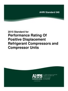
6 We dot normally use cm for length but we do use cm3 for volume. A cm3 is also called a milli litre. A cube of side 1 mm has a volume of 1 mm3 or 10-9 m3. Summarising, the units of volume are 1 m3 = 103 dm3 (litre) = 106 cm3 (millilitre) = 109 mm3. STANDARDS The following are some of the standards that apply to fluid power. BS2917/ISO 1219-1 SYMBOLS FOR hydraulic & pneumatic COMPONENTS. ISO 9461 ISO 5599 CETOP RP68P PORT IDENTIFICATION ISO 1219-2 RULES FOR LAYOUT OF CIRCUIT DIAGRAMS 3 hydraulic pumps The pump is the heart of a hydraulic system as illustrated below (with no regard to relative size).
7 The pump sucks oil out of the tank and pushes it through a directional control valve to the cylinder and the piston is forced down. The oil expelled from the bottom of the cylinder is guided back to the tank by the valve. If the valve is operated the piston in the cylinder moves up. Pressure is produced at the pressure port sufficient to overcome the force on the piston. It is the external force that produces the pressure, not the pump. The flow rate of the fluid and hence the speed of the piston is produced by the pump and this depends on the size, type and speed of the pump.
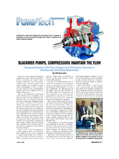
8 All the energy is put into the system through the pump and this must be provided by the motor turning it (electric or internal combustion). Figure 1 pumps are divided into two categories (i) NON POSITIVE DISPLACEMENT TYPES (ii) POSITIVE DISPLACEMENT TYPES 1. NON POSITIVE DISPLACEMENT TYPES The two main types in this category are CENTRIFUGAL and AXIAL In both cases a continuous flow is produced by a rotating impeller. There is no positive seal between the inlet and outlet and if the impeller was stopped, flow could be forced through it.
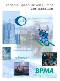
9 When the pressure rises on the outlet, flow may slip back from the outlet to the inlet and the output flow rate is reduced. For example it is possible to shut the outlet valve on a centrifugal pump and the rotor will spin but no output flow is produced. Because of internal slippage, the relationship between pressure and flow rate of such a pump is typically as shown. For this reason this type of pump is not normally used for fluid power Applications . Figure 2 4 2 POSITIVE DISPLACEMENT pumps Nearly all power hydraulic systems use positive displacement pumps .
10 In such pumps , there is ideally no internal slippage and the amount of liquid pumped is the same for each revolution regardless of the pressure. The piston pump illustrated is a good example of this. The piston sucks in and pushes out a fixed volume for every revolution of the shaft. This is called the NOMINAL DISPLACEMENT. Figure 3 It follows that Flow Rate = Nominal Displacement x Shaft Speed. In reality the mating components are not a perfect fit and so small leaks may occur past the valves and pistons.