Transcription of Unit 4: Centrifugal Pumps
1 Unit 4: Centrifugal Pumps : Purpose: To lift the liquid to the required height. Pump: A hydraulic machine which converts mechanical energy of prime mover (Motors, Engine) into pressure energy Classification of Pumps Application: 1. Agriculture & Irrigation 2. Petroleum 3. Steam and diesel Power plant 4. Hydraulic control system 5. Pumping water in buildings 6. Fire Fighting Positive Displacement: Amount of liquid taken on suction side is equal to amount of liquid transferred to deliver side. Hence discharge pipe should be opened before starting the pump to avoid the bursting of casing. Rotodynamic Pump: Increase in energy level is due to a combination of Centrifugal energy, Pressure energy and kinetic energy. fluid is not displaced positively from suction side to delivery side. Pumps can run safely even the delivery valve is closed.
2 Centrifugal Pump: Mechanical energy of motor is converted into pressure energy by means of Centrifugal force acting on the fluid. Sr. No. Centrifugal Pump Inward Flow Turbine 1 It consumes power It produces power 2 Water flows radially outward Water flows radially inward from periphery 3 Flow from low pressure to high pressure Flow from high pressure to low pressure 4 Flow is decelerated Flow is accelerated Construction and working of Centrifugal Pump Components: 1. Impeller: A wheel with series of backward curved vanes. 2. Casing: Air tight chamber surrounding the impeller. 3. Suction Pipe: One end is connected in eye and other is dipped in a liquid. 4. Delivery pipe: One end is connected to eye, other to overhead tank. 5. Foot valve: Allow water only in upward direction. 6. Strainer: Prevent the entry of foreign particle/material to the pump Working of Centrifugal Pump: When a certain mass of fluid is rotated by an external source, it is thrown away from the central axis of rotation and Centrifugal head is impressed which enables it to rise to a higher level.
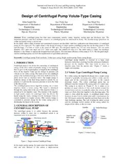
3 1. The delivery valve is closed and pump is primed suction pipe, casing and portion of delivery pipe up to the delivery valve are completely filled with water so that no air pocket is left. 2. Keeping the delivery valve is closed the impeller is rotated by motor, strong suction is created at the eye. 3. Speed enough to pump a liquid when is attained delivery valve is opened. Liquid enter the impeller vane from the eye, come out to casing. 4. Impeller action develops pressure energy as well as velocity energy. 5. Water is lifted through delivery pipe upto required height. 6. When pump is stopped, delivery valve should be closed to prevent back flow from reservoir. Types of casing 1. Volute Casing: Area of flow gradually increases from the eye of impeller to the delivery pipe. Same as shown in fig of components.
4 Formation of eddies. Fig: Volute casing Fig: Vortex casing 2. Vortex casing: Circular chamber provided between the impeller and volute chamber. Loss of energy due to formation of eddies is reduced. 3. Casing with guide blades: Casing impeller is surrounded by a series of guide vanes mounted on a ring which is known as diffuser. Water enters the impeller without shock. Various head of Centrifugal Pump The heads of a Centrifugal pump are as follows: (1)Suction head (2) delivery head (3)Static head (4) Monometric head 1. Suction head (hs) : It is vertical distance between level of sump and eye of an impeller. It is also called suction lift. 2. Delivery head (hd): It is the vertical distance between between eye of an impeller and the level at which water is delivered.
5 3. Static head (Hs): It is sum of suction head and delivery head. It is given by Hs = (hs+ hd) 4. Manometric head (Hm): The head against which the Centrifugal Pump has to work. It is given by following equations: (i) Hm = (Head imparted by the impeller to the water) (Loss of head in the pump impeller and casing) Hm = 2 2 (hLi + hLc) Where, hLi= Loss in impeller hlc = Loss in casing Hm = 2 2 (if losses are neglected) (ii) Hm = Static head + losses in pipes + Kinetic head at delivery = Hs + (hfs + hfd) + 22 = (hs+ hd) + (hfs + hfd) + 22 -------------------------------(8) Where, hs and hd = Suction and delivery head hfs and hfd = Loss of head due to friction in suction and delivery pipe.
6 Vd = Velocity pipe in delivery pipe. (iii) Hm = (Total head at outlet of pump) (Total head at inlet of Pump) Total head at outlet = + 22 + Zd = hd + 22 + Zd Total head at inlet = + 22 + Zs = hs + 22 + Zs Hm = (hd + 22 ) ( hs + 22 ) -------------------------------------(9) Inlet and outlet velocity triangles for Centrifugal Pump Work done By Impeller on liquid 1. Liquid enters eye of impeller in radial direction = 900, 1=0, V1=Vf1 2. No energy loss in impeller due to eddy formatting 3. No loss due to shock at entry 4. Velocity distribution in vanes is uniform. Let, N = Speed of impeller (rpm) = = 2 60 (rad/s) Tangential velocity of impeller 1= 1= 1 60 m/s 2= 2= 2 60 m/s 1 = Absolute velocity of water at inlet 1= 1= 1= = angle made by 1 at inlet with direction of motion of vane = Angle made by 1 at inlet with direction of motion of vane 1 , 1, 1, 1, , -----Corresponding values at outlet A Centrifugal pump is the reverse of radially inward flow reaction turbine.
7 Work done by water on runner of turbine per sec per unit weight of water = 1 ( 1 1 2 2) by impeller on water per sec per unit weight of water = - (WD in case of turbine) = - 1 ( 1 1 2 2) = 1 ( 2 2 1 1)----- ----------------------(1) Eqn. (1) is known as Euler momentum equation for pump or Euler head. Since radial entry 1=0 1 = 1 per unit weight = 1 ( 2 2) N-m/N ------------------------ (2) Q = Area x velocity of flow Q = 1 1 x 1 Continuity equation Q = 1 1 x 1= 2 2 x 2 From the outlet velocity triangle 22= 22+( 2 2)2 22 = 22- ( 2 2)2--------------------------(3) Also, 22= 22- 22-------------------------------------( 4) From equation 3 and 4 22- 22= 22- ( 2 2)2 22- 22= 22 - 22+2 2 2 22 2 2 2= 22+ 22- 22 2 2=12( 22+ 22- 22) Similarly from inlet velocity triangle 1 1=12( 12+ 12- 12) Putting in equation 1 = 1 [12( 22+ 22 22) 12( 12+ 12 12)] = 22 122 + 22 122 + 12 222 ---------------------------(5)
8 Per sec/unit weight =Increase in head +Increase in static pressure + Change in due to retardation Equation 5 is known as fundamental equation Centrifugal Pump. Losses in Centrifugal Pump 1. Hydraulic losses : Friction loss shock , eddy losses 2. Mechanical losses: Bearing friction, impeller 3. Leakage losses: leakage of liquid Efficiencies of a Centrifugal Pump 1. Manometric efficiency ( ): = = 2 2 = 2 2 Francis Turbine, = 1 1 2. Volumetric Efficiency ( ) = = + Where, Q = Actual liquid discharged at the pump outlet per second q = Leakage of liquid per second from impeller 3.
9 Mechanical efficiency ( ): = = ( 2 2 ) 4. Overall efficiency = = Hm = x Turbine, = Hm The various losses and corresponding efficiencies of a Centrifugal Pump are tabulated as follow Mechanical Losses Hydraulic Losses Motor Shaft Impeller Power Outlet Power P = ( 2 2 )
10 = Hm Effect of Outlet blade angle on Manometric Efficiency At outlet of an impeller the energy available in liquid has the pressure energy equal to the sum of manometric head (Hm) and velocity head ( 222 ) Neglecting the losses in pump we have 2 2 = Hm + ( 222 ) Hm= 2 2 222 From outlet velocity triangle, 22= 22+ 22 and 2 = u2 - 2 = u2 - Vf2 cot Substituting the above values in Hm equation Hm = ( 2 Vf2 cot ) 2 - ( 2 Vf2 cot )2+ 222 After simplification we get, Hm = 2 2 22 2 2 Substituting this value in Manometric Efficiency , = 22 22 2 2 2( 2 Vf2 cot ) ---------------------(A) In the equation (A) if we vary the value of from 200 to 900 by keeping the other parameters constant then , is between to If we further reduce the value of (below 200), it increases the efficiency but also results in long size of blades and increased friction losses.


