Transcription of Unit DC Motors and Generators
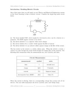
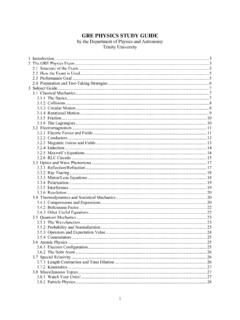
1 Festo Didactic 30329-00 61 When you have completed this unit, you will be able to use the DC Motor/Generator module to demonstrate and explain the operation of dc Motors and Generators Operating principle of dc Motors As stated in Unit 1, Motors turn because of the interaction between two magnetic fields. This unit will discuss how these magnetic fields are produced in dc Motors , and how magnetic fields induce voltage in dc Generators . The basic principle of a dc motor is the creation of a rotating magnet inside the mobile part of the motor, the rotor. This is accomplished by a device called the commutator which is found on all dc machines. The commutator produces the alternating currents necessary for the creation of the rotating magnet from dc power provided by an external source. Figure 2-1 illustrates a typical dc motor rotor with its main parts.
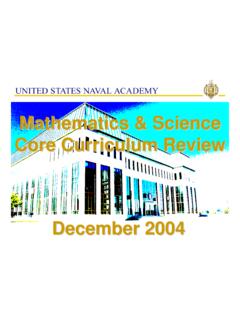
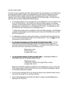
2 This figure shows that the electrical contact between the segments of the commutator and the external dc source is made through brushes. Note that the rotor of a dc motor is also referred to as the armature. Figure 2-1. The main parts of a dc motor rotor (armature). In Figure 2-2a, the brushes make contact with segments A and B of the commutator and current flows in wire loop A-B. No current flows in the other wire loop (C-D). This creates an electromagnet A-B with north and south poles as shown in Figure 2-2a. DC Motors and Generators Unit 2 UNIT OBJECTIVE DISCUSSION OF FUNDAMENTALS Unit 2 DC Motors and Generators Discussion of Fundamentals 62 Festo Didactic 30329-00 If the rotor is turned clockwise a little as shown in Figure 2-2b, current still flows in wire loop A-B and the magnetic north and south poles rotate clockwise. Figure 2-2. Operation of the commutator. As the rotor continues to rotate clockwise, a time comes where a commutation occurs, , the brushes make contact with segments C and D instead of segments A and B, as shown in Figure 2-2c.
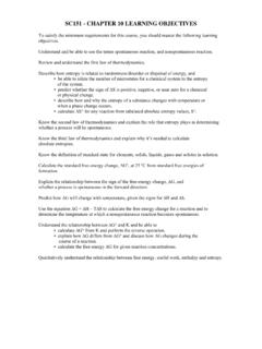
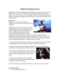
3 As a result, current now flows in wire loop C-D instead of flowing in wire loop A-B. This creates an electromagnet C-D with north and south poles as shown in Figure 2-2c. Unit 2 DC Motors and Generators Discussion of Fundamentals Festo Didactic 30329-00 63 Figure 2-3. Operation of the commutator (continued). By comparing Figure 2-2b and Figure 2-2c, you can see that the magnetic north and south poles rotate counterclockwise at the commutation. As the rotor continues to rotate clockwise, the same phenomenon repeats every angle of rotation, as shown in Figure 2-3a, Figure 2-3b, and Figure 2-3c. Unit 2 DC Motors and Generators Discussion of Fundamentals 64 Festo Didactic 30329-00 In brief, as the rotor turns, the north and south poles of the electromagnet go back and forth (oscillate) over a angle, as shown in Figure 2-4. In other words, the north and south poles are stationary, , they do not rotate as the rotor turns.
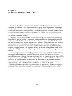
4 This is equivalent to having an electromagnet in the rotor that rotates at the same speed as the rotor but in the opposite direction. The higher the number of segments on the commutator, the lower the angle of rotation between each commutation, and the lower the angle over which the north and south poles oscillate. For example, the north and south poles would oscillate over an angle of only if the commutator in Figure 2-2, Figure 2-3, and Figure 2-4 were having 32 segments. Figure 2-4. The north and south poles oscillate around a fixed position. If this rotor is placed next to a fixed permanent magnet stator as shown in Figure 2-5, the magnetic poles of opposite polarity attract each other (in order to align) and the rotor starts to turn. After the rotor has turned by a certain angle, a commutation occurs and the north and south poles of the electromagnet go back. Once again, the magnetic poles of opposite polarity attract each other, and the rotor continues to rotate in the same direction so as to align the magnetic poles of opposite polarity.
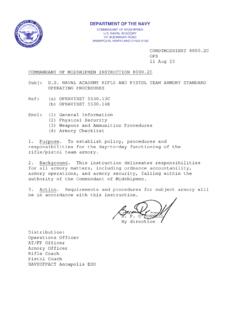
5 However, another commutation occurs a little after and the north and south poles of the electromagnet go back once again. This cycle repeats over and over. The force that results from the interaction of the two magnetic fields always acts in the same direction, and the rotor turns continually. Thus, a converter of electrical-to-mechanical energy, , an electric motor, has been achieved. The direction of rotation depends on the polarity of the voltage applied to the brushes of the rotor. Unit 2 DC Motors and Generators Discussion of Fundamentals Festo Didactic 30329-00 65 Figure 2-5. Rotation resulting from interaction of magnetic fields in the stator and the rotor. Operating principle of dc Generators Previously, we saw that the variation of magnetic flux in a coil of wire caused a voltage to be induced between the ends of the coil of wire. If a wire loop is placed between two magnets and rotated as shown in Figure 2-6, magnetic lines of force are cut and a voltage " " is induced in the loop.
6 The polarity of the induced voltage " " depends on the direction in which the wire loop moves as it cuts the magnetic lines of force. Since the wire loop cuts magnetic lines of force in both directions within a full revolution, the induced voltage is an ac voltage similar to that shown in Figure 2-6. If a commutator such as that shown in Figure 2-1 is used, it will act as a rectifier and convert the induced ac voltage into a dc voltage (with ripple), as shown in Figure 2-6. Direct current will therefore be produced at the output of the generator. The faster the rotor turns, the more lines of force that are cut and the higher the output voltage. Also, the stronger the stator magnet, the more lines of force that are present, and therefore, the higher the output voltage. Unit 2 DC Motors and Generators Discussion of Fundamentals 66 Festo Didactic 30329-00 Figure 2-6. A coil rotating in a magnetic field results in an induced voltage.
7 Festo Didactic 30329-00 67 When you have completed this exercise, you will be able to demonstrate the main operating characteristics of a separately-excited dc motor using the DC Motor/Generator module. Previously, you saw that a dc motor is made up basically of a fixed magnet (stator) and a rotating magnet (rotor). Many dc Motors use an electromagnet for the stator, as illustrated in Figure 2-7. Figure 2-7. Simplified dc motor with an electromagnet as stator. When power for the stator electromagnet is supplied by a separate dc source, either fixed or variable, the motor is known as a separately-excited dc motor. Sometimes the term independent-field dc motor is also used. The current flowing in the stator electromagnet is often called field current because it is used to create a fixed magnetic field. The electrical and mechanical behaviour of the dc motor can be understood by examining its simplified equivalent electric circuit shown in Figure 2-8.
8 Figure 2-8. Simplified equivalent circuit of a dc motor. The Separately-Excited DC Motor Exercise 2-1 EXERCISE OBJECTIVE DISCUSSION Ex. 2-1 The Separately-Excited DC Motor Discussion 68 Festo Didactic 30329-00 In the circuit, is the voltage applied to the motor brushes, is the current flowing through the brushes, and is the resistance between the brushes. Note that , , and are usually referred to as the armature voltage, current , and resistance, respectively. is the voltage drop across the armature resistor. When the motor turns, an induced voltage proportional to the speed of the motor is produced. This induced voltage is represented by a dc source in the simplified equivalent circuit of Figure 2-8. The motor also develops a torque proportional to the armature current flowing in the motor. The motor behaviour is based on the two equations given below.
9 The first relates motor speed and the induced voltage , and the second relates the motor torque and the armature current . where is a constant expressed in units of . is a constant expressed in units of or . When a voltage is applied to the armature of a dc motor with no mechanical load, the armature current flowing in the equivalent circuit of Figure 2-8 is constant and has a very low value. As a result, the voltage drop across the armature resistor is so low that it can be neglected, and can be considered to be equal to the armature voltage . Therefore, the relationship between the motor speed and the armature voltage is a straight line because is proportional to the motor speed . This linear relationship is illustrated in Figure 2-9, and the slope of the straight line equals constant.
10 Figure 2-9. Linear relationship between the motor speed and the armature voltage. Since the relationship between voltage and speed is linear, a dc motor can be considered to be a linear voltage-to-speed converter, as shown in Figure 2-10. Ex. 2-1 The Separately-Excited DC Motor Discussion Festo Didactic 30329-00 69 Figure 2-10. DC motor as a voltage-to-speed converter. The same type of relationship exists between the motor torque and the armature current , so that a dc motor can also be considered as a linear current -to-torque converter. Figure 2-11 illustrates the linear relationship between the motor torque and the armature current . Constant is the slope of the line relating the two. Figure 2-12 shows the linear current -to-torque converter. Figure 2-11. Linear relationship between the motor torque and the armature current . Figure 2-12. DC motor as a current -to-torque converter.