Transcription of UniTrane Fan-Coil
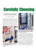
1 Air Terminal DevicesHorizontal, Vertical, and Low VerticalSizes 02-12 Basic Series Fan-Coil , Sizes 04-08 UniTrane Fan-Coil UNT-PRC001-ENDecember 2000 American Standard Inc. 2000 UNT-PRC001-ENIt isn t just a fan and a Trane Company has redesigned the traditional Fan-Coil to lead the industry in: indoor air quality (IAQ) features easy installation and maintenance high quality and durability advanced controlsRemovable, noncorrosive,positively-sloped drain pan that seasy to cleanCleanable closed-cell insulation (non-fiberglass)Two, three orfour-row coilsEasy filter accesswithout front panelremovalSmaller unit footprintEasy to remove fan assemblyQuiet operation16-gauge steel constructionFactory assembled,installed and tested pipingpackage with IAQ drain panto collect condensateFactory installed and tested controlsDamper allows upto 100% fresh airUNT-PRC001-EN3 ContentsIntroduction2 Features and Benefits644 Selection Procedure655 Model Number Description655 General Data6612 Performance Data6718 Two-Pipe Coils6719 Four-Pipe Coils6822 Hot Water Reheat Coils25 Steam Reheat Coils28 Controls6931 Electrical Data7039 Dimensions and Weights7242 Mechanical Specifications7658 Options60 BasicUniTraneFeatures andBenefitsUNT-PRC001-EN4 The UniTrane Fan-Coil meets thestandards of today s market.
2 As well asthe anticipated needs of tomorrow smarket. The tradition that companyfounder Reuben Trane began 60 yearsago continues with the latest generationof fan- coils from The Trane UniTrane Fan-Coil is the leader inthese key areas: Indoor Air Quality (IAQ) Controls Flexibility Quality ServiceabilityToday s HVAC market is concerned withissues such as indoor air quality (IAQ) andCFCs that demand a change in HVAC products. In addition, renovation hasovertaken new construction in the fan-coilmarket demanding a design that catersto renovation issues. Trane is concernedwith these issues, too. That s why wedesigned the UniTrane Fan-Coil as anintegral part of the company s systemsolutions with standard IAQ-relatedfeatures that fully comply withASHRAE Design Closed-cell insulation is standard on allunits to help prevent fiberglass in theairstream.
3 The main and auxiliary drain pans areconstructed of a noncorrosive engi-neered plastic (ABS and CyColac T). The main and auxiliary drain pans arepositively sloped in every plane toassure proper drainage and helpmaximize protection from microbialgrowth. The drain pans are removable forcleaning. Easy filter access encourages frequentchanging. The auto-economizer damper optionallows free cooling and ventilation tohelp comply with ASHRAE 62 andsave energy and operating costs. UniTrane fan- coils have a blow-thrudesign. Low vertical units are All controls are factory-mounted andtested to minimize field setup. Controls are wired with a 24 VACtransformer to keep only a singlesource power connection requirementto the unit. All wall-mounted zone sensors requireonly low voltage control wiring from thedevice to the unit control box.
4 (No linevoltage.) The Tracer controls family introducesthe latest in control technology with , , and controllers. The controller automatically determinesthe unit s correct operating mode (heat/cool) by utilizing a proportional/integral(PI) control algorithm to maintain thespace temperature at the activesetpoint, allowing total comfort control. Entering water temperature samplingeliminates the need for inefficientbleedlines to sense automaticchangeover on two-pipe changeoverunits. The random start-up feature helpsreduce electrical demand peaks byrandomly staggering multiple units atstart-up. Occupied/unoccupied operation allowsthe controller to utilize unoccupiedtemperature setpoints for energysavings. Warm-up and cool-down energyfeatures are standard with Tranecontrols.
5 Continuous fan or fan cycling is availablewith or Monitor unit operation using Tracer Summit building management systemwith or To customize unit control, Tracer Summitor Rover software will allow fieldmodification of and settings. For , use Roverto field modify default settings. Maximize Fan-Coil system efficiency withfree cooling economizers and modulat-ing valves on units with Two, three, and four-row coils allowgreater design flexibility in two andfour-pipe systems. One-row steam or hot water reheatcoils for dehudification on units controls. Fan motors are available for either highstatic ( external static pressure)or free discharge applications. Piping is factory assembled, mountedand tested. Units are also availablewithout piping. Reheat coil piping isavailable on 2-pipe units with hot waterreheat coils and either a fan speedswitch or Tracer Factory piping options include intercon-necting piping, control valves, and endvalves.
6 Deluxe piping also has unionsand a strainer. Control options range from a simple fanspeed switch to a DDC controller thatcan tie into a Tracer Summit buildingautomation system. An 8-inch (20 cm) extended end pocket isan available option on the piping end ofcabinet style units. Slope-top vertical cabinet units are alsoavailable for school and dormitoryapplications to prevent items frombeing placed on top of the coils and piping packages are air andleak-tested before mounting on the Fan-Coil . Coil piping connections are also air andleak-tested after mounting on the unit. All control end devices and movingcomponents (fans and motors) arecomputer-tested after units Filters are easily removable andchanged without removing the frontpanel on vertical cabinet units.
7 Motors are easy to disconnect from thefan board, allowing easy service. The main and auxiliary drain pans areeasily removable and wipe clean with awet cloth. The manual output test function is aninvaluable troubleshooting tool. Bysimply pressing the test button on theTracer , , or ;service personnel can manuallyexercise outputs in a 18 CoilA = 2 Row Cooling/HeatingB = 3 Row Cooling/HeatingC = 4 Row Cooling/HeatingD = 2 Row Cooling/1 Row HeatingE = 2 Row Cooling/2 Row HeatingF = 3 Row Cooling/1 Row HeatingG = 2 Row Cooling OnlyH = 3 Row Cooling OnlyJ = 4 Row Cooling OnlyK = 2 Row Cooling/Heating withElectric HeatL = 3 Row Cooling/Heating withElectric HeatM = 4 Row Cooling/Heating withElectric HeatP = 2 Row Cooling/Heating with1 Row HeatingQ = 2 Row Cooling/Heating with2 Row HeatingR = 3 Row Cooling/Heating with1 Row HeatingDigit 19 Coil Series2 = 144 FPFD igit 20 Coil Air VentA = Automatic Air VentM = Manual Air VentDigits 21, 22, 23 Electric HeatkW ( ) = 208V Derate000 = No Electric Heat010 = kW ( kW)
8 015 = kW ( kW)020 = kW ( kW)025 = kW ( kW)030 = kW ( kW)040 = kW ( kW)050 = kW ( kW)060 = kW ( kW)070 = kW ( kW)08 0= kW ( kW)100 = kWDigit 24 Reheat Coil0 = NoneB = Hot Water CoilA = Steam CoilDigit 25 Disconnect Switch0 = NoneD = Disconnect SwitchDigits 1, 2 Unit TypeFC = Fan-CoilDigit 3 Cabinet TypeA = Vertical ConcealedB = Vertical CabinetC = Horizontal ConcealedD = Horizontal CabinetE = Horizontal RecessedH = Vertical RecessedJ = Vertical Cabinet Slope TopK = Low Vertical ConcealedL = Low Vertical CabinetDigit 4 Development Sequence B Digits 5, 6, 7 Unit Size020 040 080030 060 100120 Digit 8 Unit Voltage1 = 115/60/18 = 110-120/50/12 = 208/60/19 = 220-240/50/13 = 277/60/14 = 230/60/1 Digit 9 Piping System/PlacementA = No piping, RH, No Auxiliary DrainPanB = No piping, LH, No Auxiliary Drain PanC = No piping, RH.
9 With Auxiliary DrainPanD = No piping, LH, with Auxiliary DrainPanE = No piping, RH, No Auxiliary DrainPan, Extended End PocketF = No piping, LH, No Auxiliary DrainPan, Extended End PocketG = No piping, RH, with Auxiliary DrainPan, Extended End PocketH = No piping, LH, with Auxiliary DrainPan, Extended End PocketJ = With piping package, RHK = With piping package, LHL = With piping package, RH, ExtendedEnd PocketM = With piping package, LH, ExtendedEnd Pocket FC B B 020 1 C M0 A 0 G 1 0 A A 2 M 000 0 0 1 0 0 0 A A 000 000 0 0 0 0 A 0 0 1 5 10 15 20 25 30 35 404 4 Digits 10, 11 Design Sequence M0 Digit 12 InletsA = Front Toe SpaceB = Front Bar GrilleC = Front Stamped LouverD = Bottom Stamped LouverE = Bottom Toe SpaceF = Back Duct CollarG = Back Open ReturnH = Back Stamped LouverDigit 13 Fresh Air Damper0 = NoneA = Manual, Bottom OpeningB = Manual, Back OpeningC = Manual, Top OpeningD = Auto, 2-Position, Bottom OpeningE = Auto, 2-Position, Back OpeningF = Auto, 2-Position, Top OpeningG = Auto, Economizer, Bottom OpeningH = Auto, Economizer, Back OpeningJ = Auto, Economizer, Top OpeningK = No Damper, Bottom OpeningL = No Damper, Back OpeningM = No Damper.
10 Top OpeningDigit 14 OutletsA = Front Duct CollarB = Front Bar GrilleC = Front Stamped LouverD = Front Quad GrilleG = Top Quad GrilleH = Top Bar GrilleJ = Top Duct CollarDigit 15 Color0 = No Paint (Concealed Units Only)1 = Deluxe Beige 4 = Driftwood Grey2 = Soft Dove5 = Stone Grey3 = Cameo White 6 = Rose MauveDigit 16 Tamperproof Locks/Leveling Feet0 = NoneB = Keylock Access DoorC = Keylock Panel and Access DoorD = Leveling FeetF=Keylock Access Door with LevelingFeetG = Keylock Panel and Access Door withLeveling FeetDigit 17 MotorA = Free DischargeB = High StaticUniTrane Fan-Coil Model Number DescriptionFollowing is a complete description of the Fan-Coil model number. Each digit in the model number has a corresponding code thatidentifies specific unit NumberDescriptionSelectionProcedureUNT-P RC001-EN6 Digit 26 Filter0 = None1 = 1 Throwaway Filter2 = 1 Throwaway Pleated Media Filter3 = 1 Throwaway + (1) Extra4=1 Throwaway Pleated Media + (1)Extra5 = 1 Throwaway + (2) Extras6 = 1 Throwaway Pleated Media +(2) Extras7 = 1 Throwaway + (3) Extras8 = 1 Throwaway Pleated Media +(3) ExtrasDigit 27 Main Control Valve0 = NoneA = 2-Way, 2-Position, NO (25 psig)B = 3-Way, 2-Position, NO (30 psig)C = 2-Way, 2-Position, NC (25 psig)D = 3-Way, 2-Position, NC (15 psig)E = 2-Way, 2-Position, NO (50 psig)F = 3-Way, 2-Position, NO (50 psig)G = 2-Way, 2-Position, NC (50 psig)H = 3-Way, 2-Position, NC (50 psig)