Transcription of UNRESTRAINED BEAM DESIGN – II
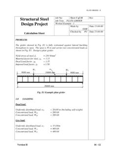
1 UNRESTRAINED beam DESIGN -II 12 UNRESTRAINED beam DESIGN II INTRODUCTION The basic theory of beam buckling was explained in the previous chapter. Doubly symmetric I- section has been used throughout for the development of the theory and later discussion. It was established that practical beams fail by: (i) Yielding, if they are short (ii) Elastic buckling, if they are long, or (iii) Inelastic lateral buckling, if they are of intermediate length. A conservative method of designing beams was also explained and its limitations were outlined. In this chapter a few cases of lateral buckling strength evaluation of beams encountered in practice would be explained. Cantilever beams, continuous beams, beams with continuous and discrete lateral restraints are considered. Cases of monosymmetric beams and non-uniform beams are covered.
2 The buckling strength evaluation of non-symmetric sections is also described. CANTILEVER BEAMS A cantilever beam is completely fixed at one end and free at the other. In the case of cantilevers, the support conditions in the transverse plane affect the moment pattern. For DESIGN purposes, it is convenient to use the concept of notional effective length, k, which would include both loading and support effects. The notional effective length is defined as the length of the notionally simply supported (in the lateral plane) beam of similar section, which would have an elastic critical moment under uniform moment equal to the elastic critical moment of the actual beam under the actual loading conditions. Recommended values of k for a number of cases are given in Table 1.
3 It can be seen from the values of k that it is more effective to prevent twist at the cantilever edge rather than the lateral deflection. Generally, in framed structures, continuous beams are provided with overhang at their ends. These overhangs have the characteristics of cantilever beams. In such cases, the type of restraint provided at the outermost vertical support is most significant. Effective prevention of twist at this location is of particular importance. Failure to achieve this would result in large reduction of lateral stability as reflected in large values of k , in Table 1. Copyright reserved Version II 12-1 UNRESTRAINED beam DESIGN -II Table 1 Recommended values of k Restraint conditions Loading condition At support At tip Normal Destabilizing Built in laterally and torsionally Free Lateral restraint only Torsional Restraint only Lateral and Torsional Restraint Continuous with lateral and torsional restraint Free Laterally restraint only Torsional Restraint only Laterally and Torsional Restraint Continuous, with lateral restraint only Free Lateral restraint only Torsional Restraint only Laterally and Torsional Restraint For continuous cantilevers not less than 1 where 1 is the length of the adjacent span For cantilever beams of projecting length, L.
4 The effective length LLT to be used shall be taken as in Table 3 (Table of New IS: 800) for different support conditions. Version II 12-2 UNRESTRAINED beam DESIGN -II Table 3 Effective length for Cantilever Beams (Table of New IS: 800, Effective Length, Llt , for Cantilever of Length L) (Section ) Restraint condition Loading conditions At Support At tip Normal destabilizing a) Continuous, with lateral restraint to top flange 1) Free 2) Lateral restraint to top flange 3) Torsional restraint 4) Lateral and torsional restraint b) Continuous, with partial torsional restraint 1) Free 2) Lateral restraint to top flange 3) Torsional restraint 4) Lateral and torsional restraint c) Continuous, with lateral and torsional restraint 1) Free 2) Lateral restraint to top flange 3) Torsional restraint 4) Lateral and torsional restraint d) Restrained laterally, torsionally and against rotation on plan 1) Free 2) Lateral restraint to top flange 3) Torsional restraint 4)
5 Lateral and torsional restraint Top restraint conditions 1) Free 2) Lateral restraint to top flange 3) Torsional restraint 4) Lateral and torsional restraint Version II 12-3 UNRESTRAINED beam DESIGN -II CONTINUOUS BEAMS Beams, extending over a number of spans, are normally continuous in vertical, lateral or in both planes. In the cases, where such continuity is not provided lateral deflection and twisting may occur. Such a situation is typically experienced in roof purlins before sheeting is provided on top of them and in beams of temporary nature. For these cases, it is always safe to make no assumption about possible restraints and to DESIGN them for maximum effective length. Another case of interest with regard to lateral buckling is a beam that is continuous in the lateral plane the beam is divided into several segments in the lateral plane by means of fully effective braces.
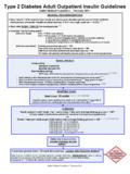
6 The buckled shapes for such continuous beams include deformation of all the segments irrespective of their loading. Effective length of the segments will be equal to the spacing of the braces if the spacing and moment patterns are similar. Otherwise, the effective length of each segment will have to be determined separately. To illustrate the behaviour of continuous beams, a single-span beam provided with equally loaded cross beams is considered (see Fig. 1). A B C 1 1WW 2 D b Fig. 1 Single - span beam Two equally spaced, equally loaded cross beams divide the beam into three segments laterally. In this case, true Mcr of the beam and its buckling mode would depend upon the spacing of the cross beams. The critical moment McrB for any ratio of 1 / b would lie in between the critical moment values of the individual segments.
7 The critical moments for the two segments are obtained using the basic equation given in the earlier chapter. GJE 1GJ)IE( += (In the outer segment, m = Using 1 / m and the basic moment, the critical moment is determined) GJE 1GJ)EI( M222y2cr2 +=(2)(1) (This segment is loaded by uniform moments at its ends basic case) Version II 12-4 UNRESTRAINED beam DESIGN -II Mcr1 and Mcr2 values are plotted against 1 / band shown in Fig. 2 for the particular case considered with equal loading and a constant cross section throughout. Dimensionless Critical Moment Mcr / McruB8 6 4 2 0 beams Mcr = McruBMcr1 Mcr2 Zero interaction Dimensionless Load Position 1/ bIt is seen that for 1 / b = , Mcr1 and Mcr2 are equal and the two segments are simultaneously critical. The beam will buckle with no interaction between the two segments.
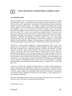
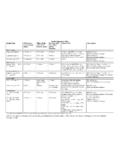
8 For any other value of 1 / b there will be interaction between the segments and the critical load would be greater than the individual values, as shown in the figure. For values of 1 / b < , outer segments will restrain the central segment and vice-versa when 1 / b > Interaction between Mcr1and Mcr2 The safe load for a laterally continuous beam may be obtained by calculating all segmental critical loads individually and choosing the lowest value assuming each segment as simply supported at its ends. It is of interest to know the behaviour of beams, which are continuous in both transverse and lateral planes. Though the behaviour is similar to the laterally UNRESTRAINED beams, 1 2 1 2 Continuous beam and loading Deflected shapeBuckledshapeFig. 3 Continuous beam deflected shape and buckled shape 1 1 2 2 w1 (udl) w2(udl) w2(udl) Version II 12-5 UNRESTRAINED beam DESIGN -II their moment patterns would be more complicated.
9 The beam would buckle in the lateral plane and deflect in the vertical plane. There is a distinct difference between the points of contraflexure in the buckled shape and points of contraflexure in the deflected shape. These points will not normally occur at the same location within a span, as shown in Fig. 3. Therefore, it is wrong to use the distance between the points of contraflexure of the deflected shape as the effective length for checking buckling strength. PROVISIONS OF NEW IS: 800 (LSM VERSION) For beams, which are provided with members giving effective lateral restraint to the compression flange at intervals along the span, in addition to the end torsional restraint required, the effective length for lateral torsional buckling shall be taken as the distance, centre-to-centre, of the restraint members in the relevant segment under normal loading condition and times this distance, where the load is not acting on the beam at the shear and is acting towards the shear centre so as to have destabilizing effect during lateral torsional buckling deformation.
10 Where a member is provided as intermediate lateral supports to improve the lateral buckling strength, these restraints should have sufficient strength and stiffness to prevent lateral movement of the compression flange at that point, relative to the end supports. The intermediate lateral restraints should be either connected to an appropriate bracing system capable of transferring the restraint force to the effective lateral support at the ends of the member, or should be connected to an independent robust part of the structure capable of transferring the restraint force. Two or more parallel member requiring such lateral restraint shall not be simply connected together assuming mutual dependence for the lateral restraint. The intermediate lateral restraints should be connected to the member as close to the compression flange as practicable.