Transcription of USB Interface III - microHAM
1 microHAM 2016 All rights reservedUSB Interface IIImicroHAMfax: +421 2 4594 5100e-mail: March 20161microHAM 2016 All rights reservedTABLE OF CONTENTSCHAPTER AND FUNCTIONS .. WARNINGS .. DESCRIPTION .. 4 Rear Panel .. 4 Front Panel .. 5 Preparing for 5 Macintosh (OS X) 6 Windows installation .. 6 Installing microHAM USB Device Router ..6 Configuring USB Audio CODEC ..7 Configuring microHAM Device Router ..8 Creating and Using Virtual Ports .. DEVICE ROUTER .. 9 Menu: Router .. 9 Menu: Preset .. 9 Menu: Device.
2 11 Menu: Virtual Port .. 12 Menu: Help .. 12 Ports 13 Radio Port .. 13CW 14 PTT 14 Squelch Port .. AUDIO CONSIDERATIONS .. 178. PACKAGE CONTENTS .. 19 Hardware Specifications .. 19 DECLARATION OF CONFORMITY .. 20 APPENDIX A - DB15 RADIO CONNECTOR .. 21 APPENDIX B FSK WITH 22 APPENDIX C RFI 23 APPENDIX D Cables and Bridges .. 242microHAM 2016 All rights reserved1 - FEATURES AND FUNCTIONS No Serial or Parallel port necessary, just one USB port Complete "Computer <-> Radio" isolation bidirectional transformer isolation of audio signals optical isolation of ALL digital signals: Radio Control, CW, PTT, FSK Compatible with all MS Windows based logging or control software the special microHAM "USB Device Router" program creates virtual COM ports for full operation with standard Windows applications.
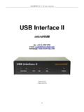
3 Customizable presets allow instantly changing USB Interface III parameters to match the program currently in use Compatible with non-Windows logging or control software uses industry standard USB UART (FTDI) drivers uses industry standard USB Audio (TI/Burr-Brown) drivers Integrated computer control port for all radios CI-V, FIF-232, IF-232, RS-232 fully supports Icom, Kenwood, TenTec, Yaesu and other radios no separate level converter required Squelch input for additional software control Strong RFI immunity integrated chokes and filters for best RFI immunity advanced shielding and circuit design for RFI product suppression Connections: Computer USB Radio DB15 Front panel LEDs for easy visual feedback of CW, PTT, SQL, POWER and radio control data Metal/Aluminum case, powder coated and silk screened Free, no time limit, on-line firmware/software upgrades2 - IMPORTANT WARNINGSYou must set the CAT level jumpers inside the USB Interface III before using it for the first you power USB Interface III from an external power supply ALWAYS check the polarity of the external V your radio includes upgradeable firmware, DO NOT perform any upgrade through USB Interface 2016 All rights reserved3 - PANEL DESCRIPTIONRear Panel(1)- USB: USB B connector for attachment to computer.
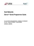
4 Connect a standard USB A-B cable. (2)- RADIO: DB15F connector for radio interconnection a detailed description is in Appendix AFront Panel(1) POWER: YELLOW color indicates when unit is powered SQL: GREEN color indicates when squelch is activeCONTROL: RED color indicates when radio sends data to computer GREEN color indicates when computer sends data to radio PTT: RED color indicates when PTT is active CW: RED color indicates when CW is active(2) TX: Transmit Audio Level(3) RX: Receive Audio Level 4microHAM 2016 All rights reserved4 - INSTALLATIONI nstalling USB Interface III consists of several steps: 1) prepare USB Interface III to work with your radio2) Install the necessary driver software for your operating system.
5 3) Configure the driver and/or application software for your specific system4) configure the USB Audio CODEC 5) configure Router Preparing USB Interface III for Use the top cover from the USB Interface III and set the CAT jumpers as shown in the following chart. The CAT Interface jumpers must be configured to select the proper level for each radio levels: All transceivers with RS-232 CAT inputs. IF-232 levels:Kenwood: TS-140, 440, 450, 680, 690, 711,790, 811, 850, 940, 950 FIF-232 levels: Yaesu: FT-100, 736, 747, 757 GXII, 767, 817,840, 857, 890, 897, 900, 980, 990, 1000, 1000 DCI-V levels: Icom: all radios TenTec: all radios with mm jack NOTE: the CAT Interface is not configured at the DB15M on the radio cable set into the DB15 connector on the rear panel of the USB Interface III and plug ALL connectors from the cable set to the appropriate jacks at the rear panel of your transceiver.
6 Each connector on the radio Interface cable is marked same as the matching jack on your transceiver. the radio cable ends with leads for external power, connect these leads to a 12-16V DC power supply. Be sure to observe the proper but do not connect the USB cable from USB Interface III to your computer. you will be installing on a Windows computer, skip to Installing microHAM USB Router 5IF232CI-VFIF232RS232microHAM 2016 All rights reservedMac OS X the microHAM CD in yourCDROM/DVD drive and navigate toDrivers/OS-X or use your web browser to goto down load the latest driver image clicking on it. OS-X , or openFTDIUSBS erialDriver_10_4_10_5_10_6and follow the instructions to install.
7 In the USB cable on the radio or external power supply. your software developer's instructions to configure their application to work with USB Interface III. MICROSOFT WINDOWS INSTALLATIONI nstalling microHAM USB Device Router install Router click on the Install USB Device Router link on the installation CD or download the most recent installation package from the web site: you download an updated package, right click on " " (xx_xx is version) and choose Run as administrator to start Windows setup utility will start and ask into whichfolder Router and its supporting files should beinstalled. Note: unless you have a very strong reasonto install Router elsewhere, please accept the defaultlocation.
8 The Router installation is completed, click"Finish" to launch Router for the first time. in the USB cable and proceed to configuring Router for your station and software. 6microHAM 2016 All rights reservedConfiguring USB Audio CODEC Windows will automatically install the USB Audio Device driver to support the USB Audio CODEC in USB Interface III. Windows automatically selects any newly installed audio device as the default device for Sound Playback and Sound Recording. This is undesirable as Windows Sounds would be played through USB III and onto the air! Open "Sound" in the Control Panel or right click on the Speaker Icon on the Taskbar and select "Playback." Reset the Default Device and Default Communications Device (if it exists) to Speakers of your computer's primary sound device.
9 Select Recording. Reset Default Device andDefault Communications Device to an input on theinternal (primary) sound card in your computer. Double click on Microphone USB Audio Codecdevice, click on Advanced tab and verify that theDefault Format is set to 2 2016 All rights reserved Configuring microHAM USB Device Router The microHAM USB Device Router (Router) program provides a Windows compatible configuration tool for microHAM USB Devices (USB Interface III as well as microKEYER, CW Keyer and USB Interfaces) and software Interface to other Windows applications (loggers, digital mode software, etc.). The software Interface is provided as Virtual Serial configure and use USB Interface III with Windows compatible application programs it is necessary to have installed the USB driver, started the Router, and applied power to USB Interface III by turning on the attached radio or external power supply.
10 Router is then configured to match the requirements of the application (logger or digital mode) software. Creating and Using Virtual Serial Ports microHAM Router provides a set of virtual serial ports which allow Windows applications (loggers and digital software) to work with USB Interface III just as they would work with "real" (hardware) serial ports. In order to use these virtual Ports, you must first create the ports and then assign a function (radio control, PTT, CW, FSK, etc.) to each virtual port. DO NOT define a port that is already in use (for example, COM1 or COM2 which are hardware ports on many motherboards) or a virtual port used by another USB device. Router will not allow using a COM port number which is already present in the system but ports are sometimes hidden.