Transcription of USBCNC - Eding CNC
1 USBCNC . User Manual Document Release Published by: Bert Eding Eindhoven The Netherlands Title: USBCNC Manual Author: Bert Eding Date: Thursday, 08 March 2012. Document History Version Date Author Comment 1 2006-03-10 Bert Eding Initial version 2011-09-19 Bert Eding - Modified UI. - OpenGL. - Nesting - Gotoline->start and Pause->start completely redesigned. 2011-10-23 Bert Eding Added G68 R_ X_ Y_ rotation. 2011-11-05 Bert Eding Added trafic light support, ussable on AUX. ouputs of CPU card. Only CPU5B can support all 3 colors. Extended dlgmsg, 12 parameters, picture. Users pay attention the behavior of the cancel button has changed, the program will continue with #5390 = -1, so after dlgmsg please use if [#5398 == 1] ;User pressed OK.. do your stuff here endif 2011-11-13 Bert Eding Some modifications for added UI buttons in variable window.
2 2011-12-11 Bert Eding Corrected a few mistakes. 2012-03-03 Bert Eding Removed , document history because this table became too long. Synced version number with actual software version number. Removed unnecessary text. Corrected mistakes and added missing descriptions reported by customers. Updated the hardware tips appendix with more detailed information about good EMC practices. Copyright USBCNC . All rights reserved. Reproduction in whole or in part prohibited without the prior written consent of the copyright owner. ACKNOWLEDGEMENTS. The G-Code part of this user manual has been derived from the full report of the RS274/NGC language. Parts that are less relevant to USBCNC users or parts that are not supported are left out. USBCNC Manual Table of contents Table of contents 4. 1 Introduction 8. Context and scope 8.
3 Definitions, acronyms and abbreviations 9. Minimum PC requirements 9. Installation of USBCNC 10. USB 10. Ethernet 11. Set admin mode 15. 2 The user interface 16. Setup Page's 16. UI and Connection 17. Motor setup 17. Homing and ESTOP setup 18. Backlash setup 19. Trajectory setup 20. Kinematic Setup 20. Tool change Area 20. Tangential knife setup 20. Safety Input 21. Spindle and PWM setup 21. UI setup items 22. Load/Run Automatically 23. IO setup 23. Traffic light setup 24. Interpreter settings 24. JobTimeEstimation 24. Hand wheel Setup 25. Probing Setup 25. CPUOPT 26. Operate Page 28. Operate page introduction 28. Reset Button F1 29. Escape Button 29. The menu's 30. Main Menu 30. Home menu 30. Zero menu 30. Auto menu 30. IO menu 34. Graphic menu 34. Jog menu 35. Jog pad 35. User menu 36. Operate page tasks 37.
4 Startup 37. 08 March 2012 Release 4. USBCNC Manual Homing 37. Load and run a g-code file 37. Program Page, DXF and HPGL import 42. Tools Page 45. Milling 45. Tool change 45. Automatic user defined Tool change ATC 45. Turning 46. The variable Page 47. IO Page 48. homing and coordinate systems 49. Manual homing the machine 50. Automatic homing the machine and HomeIsEstop 51. Tandem axes homing 51. Work versus Machine coordinate system and zeroing 52. Keyboard shortcuts 54. Zero tool macro 55. Tool measurement Macro 56. 3 Input: the RS274/NGC Language 59. Overview 59. RS274/NGC Language view of a Machining Center 59. Parameters/Variables 59. Tool data 62. Tool Orientation for lathes 62. Coordinate Systems 63. Format of a Line 63. Line Number 63. Word 64. Number 64. Parameter Value 65. Expressions and Binary Operations 65.
5 Unary Operation Value 66. Parameter Setting 66. Comments and Messages 67. Item Repeats 67. Item order 67. Commands and Machine Modes 68. Modal Groups 68. G Codes 69. Rapid Linear Motion - G0 70. Linear Motion at Feed Rate - G1 72. Arc at Feed Rate - G2 and G3 72. Radius Format Arc 72. Center Format Arc 73. Dwell - G4 74. Set Coordinate System Data -G10 74. Plane Selection - G17, G18, and G19 75. Length Units - G20/G21 and G70/G71 75. Return to Home - G28 and G30 75. 08 March 2012 Release 5. USBCNC Manual G33, Spindle-Synchronized Motion 75. Straight Probe - 76. The Straight Probe Command 76. Using the Straight Probe Command 76. Example Code 77. Cutter Radius Compensation - G40, G41, , G42, 78. Example code for milling 79. Example code for turning 80. Tool Length Offsets - G43, , and G49 80. Move in Absolute Coordinates - G53 81.
6 Select Coordinate System - G54 to 81. Set Path Control Mode - G61, and G64, or G64 Px 81. Look Ahead feed 83. Coordinate system rotation G68 85. Threading (Lathe) G76 85. Cancel Modal Motion - G80 87. Canned Cycles - G81 to G89 87. Preliminary and In-Between Motion 88. G81 Cycle 89. G82 Cycle 89. G83 Cycle 89. G85 Cycle 90. G86 Cycle 90. G87 Cycle 90. G88 Cycle 91. G89 Cycle 91. Set Distance Mode - G90 and G91 91. Coordinate System Offsets - G92, , , 92. Set Feed Rate Mode - G93 and G94 92. Set Canned Cycle Return Level - G98 and G99 93. Input M Codes 93. Program Stopping and Ending - M0, M1, M2, M30, M60 93. Spindle Control - M3, M4, M5 94. Tool Change - M6 94. Coolant Control - M7, M8, M9 94. Override Control - M48 and M49 95. IO M Functions 95. Standard CNC IO - , 95. General purpose IO of CPU5B - M54, M55 and M56 95.
7 Other Input Codes 96. Set Feed Rate - F 96. Set Spindle Speed - S 96. Select Tool - T 96. Order of Execution 96. 4 Language extensions 97. Flow control 97. supported operations on expressions 97. unary operations 97. binary operations: 98. An example: 99. Special interpreter commands, non G-Code 99. Special interpreter MDI commands. 100. Macro file and automatic tool change 100. 08 March 2012 Release 6. USBCNC Manual A Cutter Radius Compensation 103. Introduction 103. Data for Cutter Radius Compensation 104. Programming Instructions 104. Turning Cutter Radius Compensation On 104. Turning Cutter Radius Compensation Off 105. Sequencing 105. Use of D Number 105. Material Edge Contour 105. Programming Entry Moves 105. General Method 105. Simple Method 106. Nominal Path Contour 107. Programming Errors and Limitations 109.
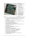
8 Hardware installation tips 112. 08 March 2012 Release 7. USBCNC Manual 1 Introduction This manual describes the usage of the CNC control system. Most hardware details can be found in the hardware documentation on the Eding CNC download page. CONTEXT AND SCOPE. This section describes the context, hardware and software of a USBCNC controlled Machine. 1. Operator 2. PC connected via USB or Ethernet to electronic cabinet which contains the USBCNC CPU. The PC runs the USBCNC Control Software. 3. Electronics cabinet, with power supplies, drives and USNCNC CPU. 4. USBCNC CPU. 5. CNC Machine The connection from CPU to the PC is USB or Ethernet depending on the CPU model. The CPU delivers STEP/Direction signals to the power stage of each motor (drive), the motor connections of the drive go to the motors inside the machine.
9 Other connections like home-sensor/switches go directly from CPU to the machine. For detailed info on all IO signals see the info in the technical flyers of the CPU, available on the download page. The Scope of the USBCNC product is the USBCNC software on the PC and the USBCNC CPU. 08 March 2012 Release 8. USBCNC Manual DEFINITIONS, ACRONYMS AND ABBREVIATIONS. CNC Computerized Numerical Control CPU Central Processor Unit, a PCB board with a Processor on it. DXF Drawing Exchange Format) is a CAD data file format developed by Autodesk FIFO First In First Out Buffer HPGL Hewlet Packard Graphical Language GUI/UI Graphical User Interface INTERPRETER A software function that is able to read a text file and execute the commands contained therein. JOBFILE A job is the text file (G code) that will be executed by the interpreter.
10 GUI Graphical User Interface. PWM Pulse Width Modulation G-Code CNC specific language to control the movements and IO of a milling machine. LAF Look Ahead Feed, advanced motion algorithm that ensures minimal machining time. MINIMUM PC REQUIREMENTS. GHz Atom. Pentium, duo-core recommended for Ethernet. 1024 MB RAM for XP, 4G for Windows 7. Windows XP or Windows 7, 32 or 64 bit. Minimum Screen resolution 1024 x 768. Graphic card with Open GL support is preferred. USB-2 connection / Ethernet connection for Ethernet CPU's Intel 100 Mbit Ethernet card for Ethernet CPU's. Windows XP and Windows 7 is proven to work fine with USBCNC . Windows Vista is not. USBCNC requires soft-real-time behavior of your PC. Sometimes a bad driver of your video-card, sound etc may be the cause of problems with USBCNC . USBCNC requires a USB communication speed of about 150 times/second to and from the USBCNC CPU.