Transcription of USE OF BROMS’S METHOD AND FINITE DIFFERENCE METHOD IN THE ...
1 Vla ki S. Use of broms's METHOD .. Archives for Technical Sciences 2014, 11(1), 65-72. Professional paper UDC: DOI: 4573208. USE OF BROMS'S METHOD AND FINITE DIFFERENCE . METHOD IN THE DIMENSIONING OF PILES FOR. FOUNDATION PIT INSURANCE. Vla ki Svjetlana1. 1. Procontrol, Banja Luka, E. mail: ABSTRACT: Implementation of major construction projects thanks are due to the technological development of materials and equipment to perform. Development of equipment for piles, allowed this type of structure a large application, as in the system of basic structural elements, as well as providing (temporary or permanent). construction site. Influences on the pile construction, since the purpose is very different. In the case that they are intended to ensure the construction work area, the dominant influence of lateral pressure or horizontal load.
2 Just such an example will be processed in this paper with a tendency to show the dependence of the results on the choice of calculation methods of calculation. Key words: buiding space, pile, load, dimensioning INTRODUCTION. Modern construction is characterized by the construction of buildings and more complex structural components and exceptional loads. Specially the problem often creates unfavorable geotechnical conditions in which such objects can be found, and the application of pile foundation for their most appropriate solution. A pile is a bearing element for supporting the transfer of power structure in the soil supporting the lower bearing and non-bearing layers. The piles can affect as an individual or in a group- based, connected headset structure. Problem foundation of a certain object can always be solved in several ways, but after assessment of conditions in the soil and structure analysis requires only one solution be the optimal.
3 This selected solution can be further analyzed and rationalized. BEARING CAPACITY OF PILES - GENERAL CONSIDERATIONS. Bearing capacity of pile groups subjected to normal or vertical and lateral load depends on the behavior of a single pile. Bearing capacity of one pile depends on the type, size and length of the pile; Soil type;. Installation METHOD (installation);. Technical Institute Bijeljina, Archives for Technical Sciences. Year VI N0 11. 65. Vla ki S. Use of broms's METHOD .. Archives for Technical Sciences 2014, 11(1), 65-72. Bearing capacity depends primarily on the installation METHOD (installation) and soil types. Bearing capacity one of the pile increases as the size and length. The position of underground water also affect bearing capacity. We have to analyze the interaction between the pile and the soil, determine failure deformation and evaluate the resulting soil deformation under constant load, additional load to design a safe and cost-effective the foundation on pile.
4 The use of piles should provide adequate security against damage; safety factor that is used depends on the importance of the structure and reliability of parameters and the load of soil composition which is used in the design. Settlement should be in accordance with appropriate behavior superstructure to avoid the disturbance of their efficiency [1]. LATERAL LOADED PILES INPUT DATA. Conditions that have to be satisfied are that the vertical settlement and horizontal displacement shall not exceed the allowable values and that there must be no collapse the pile and the soil around the pile. The input data used as relative density, angle of internal friction, modulus of compressibility obtained by SPT. test on 8 borehole and on total depth of 8m [2,3]. Geomechanical characteristics of soil: = 19,0 kN/m3. ф= 35.
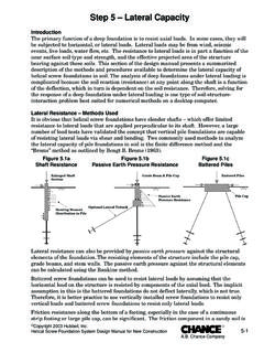
5 Ms = ,0 kN/m2. Ka = tg2 (45 - ф /2) = tg2 (45 - 35 /2) = 0,271. Ed= Ms Ks =. Ax = Lp Table values of the input data Diameter D= 1,2 m The distance between the piles = 2,0 m Modulus of compressibility Ms = 24000 KN/m2. Poisson's coeddicient = Modulus of deformation Ed = KN/m2. Moment of inertia (the cross section of the pile) J = m . Modulus of elasticitz for concrete Eb = 31500000 KN/m2. Lateral stiffness of soil by Vesic Ks = KN/m2/m . The corresponding length of the bars Lp = m Required cross sectional area Ax = cm2. Technical Institute Bijeljina, Archives for Technical Sciences. Year VI N0 11. 66. Vla ki S. Use of broms's METHOD .. Archives for Technical Sciences 2014, 11(1), 65-72. Figure 1 Model of the pile with a load of 10KN/m2. Figure 2 Disposition of piles Technical Institute Bijeljina, Archives for Technical Sciences.
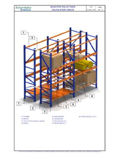
6 Year VI N0 11. 67. Vla ki S. Use of broms's METHOD .. Archives for Technical Sciences 2014, 11(1), 65-72. The three diameter of pile used for testing (1200, 900 and 800 mm) to obtain credible results. This paper will be presented results for diametar of pile 1200 mm, because of data large. BROMS'S METHOD . The diagrams in Figure 3 allows the determination of horizontal deformation in the workload for incoherent soil [1,4]. Figure 3 Determination of the horizontal deformation for incoherent soil Table 2 k1 step change in funding in the sand (MN/m3). The relative density small medium grand SPT values (number of 10-30. shots). Soil, dry or wet 15 45 175. soil flooded 10 30 100. Lateral (horizontal) displacement of piles embedded in incoherent soils can be obtained from Figures 3. The dimensionless factor t is plotted as a function of L factors for variable values e / L [1,4,5].
7 Where : Yg displacement at the level of area = (1). - coefficient of variation of soil module Pt- horizontal (lateral) load applied at or above the area L length of the pile e eccentricity of load Technical Institute Bijeljina, Archives for Technical Sciences. Year VI N0 11. 68. Vla ki S. Use of broms's METHOD .. Archives for Technical Sciences 2014, 11(1), 65-72. Limit the horizontal (lateral) resistance of piles in the incoherent soil: Figure 4 For long pile In Figure 4 are given dimensionless values, depending on the Pu/ d3kp My/ d4kp, where is: - effective weight of soil kp = Rankine's coefficient of passive resistance of soil = kg2(45+ф/2). CALCULATION. 1200. q=10kN/m2. =19kN/m3. ф= 35 . Kp = tg2 (45 + ф /2) = tg2 (45 + 35 /2) = I= E=31500000 KN/m2. EI=3206,3 MN/m2. From SPT N=15 hits k=45MN/m3 (Table 2).
8 = Iz Dr= nh=31 MN/m3 (Figure 3). From the formula = Pt= and effects in the e= M= From Figure 4 for : Pt/kp d3 = L/d= L= For L= t = (Figure 3) = 3 4. For Pt/kp d = My/kp d =49 My= (Figure 4). Technical Institute Bijeljina, Archives for Technical Sciences. Year VI N0 11. 69. Vla ki S. Use of broms's METHOD .. Archives for Technical Sciences 2014, 11(1), 65-72. CALCULATION USING THE FINITE DIFFERENCE METHOD . The first step is to divide the element (pile) to n FINITE elements and then access the account, in the calculation of this METHOD . = 19,0 kN/m3. ф= 35 . Ms = ,0 kN/m2. Ka = tg2 (45 - ф /2) = tg2 (45 - 35 /2) = 0,271. Ed= Ms Ks =. Table 3 Values of the parameters required for the solution Ms = 24000 KN/m2. = Ed = KN/m2. J = m . Eb = 31500000 KN/m2. Ks = KN/m2/m . c=. where is: c the width of the pile element n the number of element L length of the pile Lq = p Value , which exists in a matrix equation is: = = From Table [6], L matrix elements on the main diagonal are: ,10= + l1,1=l9,9= + for k=2,3,4,5,6,7,8.
9 Lk,k= + Other elements in the matrix are obtained using the coefficients in Table [6], and matrix L looks like: Technical Institute Bijeljina, Archives for Technical Sciences. Year VI N0 11. 70. Vla ki S. Use of broms's METHOD .. Archives for Technical Sciences 2014, 11(1), 65-72. The value of the ordinate external load in the dividing points is: p1 p10 = KN/m p01= * (by uniformly distributed load). p02= = KN (by moment). po= + KN. So ordinate external load point 0 is equal to: po= KN/m The elements of the matrix are: p0= * p1= * p1 p10= In the matrix form p q=. To calculate the matrix was used Wolfram Mathematica program. q=Inverse . MatrixForm Displacement of each point individually calculated then by: q=y * k y=. y0= y1= .. y10= Technical Institute Bijeljina, Archives for Technical Sciences. Year VI N0 11.
10 71. Vla ki S. Use of broms's METHOD .. Archives for Technical Sciences 2014, 11(1), 65-72. CONCLUSION. We can see a big DIFFERENCE comparing the results obtained by Broms's METHOD and the FINITE DIFFERENCE METHOD . Confirm the accuracy of some of the calculation methods will be obtained by measuring the characteristic values of the movements in project implementation. The lesson of these results is that not all methods always adequate to solve the problem in practice, some methods do not provide a realistic result, however, if these values are higher than expected, we are on the side of safety. Also, the results show that the value of the coefficient of subgrade influences at results and the extreme importance of choosing the same. It is important to determine the more precisely values of the parameters that describe the soil on which to build in order to reduce errors in the calculation and large and unnecessary costs.