Transcription of Eaton Fuller Heavy-Duty Transmissions TRIG2400
1 Installation GuideEaton Fuller Heavy-Duty TransmissionsTRIG2400 June 2007FR-11210B FR-12210B FR-13210B FR-14210B FR-15210B FR-9210B FRF-11210B FRF-12210B FRF-13210B FRF-14210B FRF-15210B FRF-9210B FRO-11210B FROF-11210B FROF-11210C FROF-12210B FROF-12210C FROF-13210B FROF-13210C FROF-14210B FROF-14210C FROF-15210B FROF-15210C FROF-16210B FROF-16210C FRO-11210C FRO-12210B FRO-12210C FRO-13210B FRO-13210C FRO-14210B FRO-14210C FRO-15210B FRO-15210C FRO-16210B FRO-16210C FRO-17210C FRO-18210C Table of ContentsTable of Contents Transmission SpecificationsTransmission Nomenclature .. 1 Lubrication Requirements .. 4 Interface FeaturesAir Specifications .. 6 Shifters .. 9 Switches* .. 10 Power Take Off Openings .. 13 Output Shaft Spline .. 15 AppendixTransmission Dimensions - Side View* .. 22 Shift Bar Housing - Standard Control.
2 24 Design Remedies for Shift Lever Jumpout .. 29 Optional Internal Cooler - Side 31 Transmission Specifications1 Transmission NomenclatureModel Designation NomenclatureFR/FRO-1X210 CRatios and StepsTen Speed ModelsGear Position FR-1X210B FRO-1X210B FRO-1X210 CFRO-17210C &18210 CRatioStep In%RatioStep In%RatioStep In%RatioStep In% Roadranger Twin CountershaftFRO1X - 2 10 C Ratio SetForward SpeedsDesign Level1/100 Times Nominal Torque CapacityOverdriveTransmission Specifications2 Installation LengthTransmission Dry Weight in kg [lbs.]Transmission Center of Gravity LocationTransmission Inertia (In Neutral)Oil Capacity and Fill All Models & SeriesFrom the Front Face of a Standard#1 Clutch Housing to the Front Face Of End Yoke in mm. [inch] [ ]Series 900-1400 1500-1700 Transmission Weight268 [589]268 [589]272 [599]272 [599]SAE #1 Aluminum Clutch Housing [23] [23]SAE #1 Cast Iron Clutch Housing [76] [76]Total Transmission Weight With Aluminum Clutch Housing278 [612]282 [622]Total Transmission Weight With Cast Iron Clutch Housing302 [665]306 [675]with SAE No.
3 1 Aluminum Clutch Housing Less Shift TowerCoordinatesViewed From Measured FromDirectionValues In mm [inch]LongitudinalLeft SideFront Face of Main CaseRearward251 [ ]VerticalLeft SideMainshafts Center [ ]LateralRearMainshafts Center [ ]Inertia in kg. m [ sec ].13 [.093]Nominal Oil Volume In liters [pints] [ ]Oil FillOEMTo The Bottom Edge Of Filter Plug HoleTransmission Specifications Transmission Specifications3 Torque CapacityTransmission Dry Weight in kg (lbs) with Internal Cooler OptionTransmission Center of Gravity Location with Internal Cooler OptionOil Capacity and Fill with Internal Cooler OptionEngineering Approval Required For Specific ApplicationFR-9210B1288 [950 Lb. ft.]FR-11210 BFRO-11210 BFRO-11210C1559 [1150 Lb.]
4 Ft.]FR-12210 BFRO-12210 BFRO-12210C1695 [1250 Lb. ft.]FR-13210 BFRO-13210 BFRO-13210C1830 [1350 Lb. ft.]FR-14210 BFRO-14210 BFRO-14210C1966 [1450 Lb. ft.]FR-15210 BFRO-15210 BFRO-15210C2102 [1550 Lb. ft.]FRO-16210 BFRO-16210C2237 [1650 Lb. ft.]FRO-17210C2373 [1750 Lb. ft.]FRO-18210C2508 [1850 Lb. ft.]Series1800 Transmission Weight299 [660] 299 [660]SAE #1 Aluminum Clutch Housing [23]SAE #1 Cast Iron Clutch Housing Weight [76]Total Transmission Weight with Aluminum Clutch Housing 310 [683]Total Transmission Weight with Cast Iron Clutch Housing 334 [736]with SAE No. 1 Aluminum Clutch Housing Less Shift TowerCoordinatesViewed FromMeasured FromDirectionValues In mm [inch]Longitudinal Left Side Front Face of Main [ ]VerticalLeft SideMainshafts Center [ ]LateralRearMainshafts Center LineLeft [ ]Nominal Oil Volume in liters [pints] [32]Oil FillOEMTo the Bottom Edge of Filter Plug HoleTransmission Specifications4 Transmission SpecificationsLubrication RequirementsProper lubrication procedures are the key to a good all around maintenance Fuller Transmission are designed so that the internal parts operate in an oil circulating bath created by the motion of the gears and shafts.
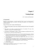
5 Thus, all parts are amply lubricated if these procedures are closely oil maintenance interval the correct grade and type of from a reputable dealer. Operating TemperaturesTransmissions must not be operated at temperatures above 250 F [120 C]. Operation at temperatures above 250 F [120 C] caus-es loaded gear tooth temperatures to exceed 350 F [177 C] which will ultimately destroy the heat treatment of the gears. If the elevated temperature is associated with an unusual operating condition that will recur, a cooler should be added, or the capacity of the existing cooling system following conditions in any combination can cause operating temperatures over 250 F [121 C]. Operating consistently at slower speeds High ambient temperatures Restricted air flow around transmission High horsepower Use of engine retarderTransmission coolers must be used to reduce operating temperatures when the above conditions are : For addition lubrication information, see Specifications5 Proper Oil LevelMake sure oil is level with the filler opening.
6 Because you can reach oil with your finger does not mean oil is at proper level. (Oneinch of oil level is about one gallon of oil.)When adding oil, types and brands of oil should not be mixed because of possible Operating AnglesIf the transmission operating angle is more than 12 degrees, improper lubrication will occur. The operating angle is the transmis-sion mounting angle in the chassis plus the percent of upgrade (expressed in degrees).For operating angles over 12 degrees, the transmission must be equipped with an oil pump or cooler kit to insure proper Lubricant Types and Application*See Form TCMT-0019, Eaton Fuller heavy duty and mid range Transmissions "Lubrications Requirements".WARNING: Do not use EP oils in the Transmissions !Transmission Operating LimitsContact Eaton Applications Engineering for the correct applications for Application Approval RequestContact Eaton Applications Engineering for the correct application approval Oil LevelHoleProper Oil LevelHoleInterface Features6 Interface FeaturesAir SpecificationsMaster Valve: Same As Current ProductVehicle Air Supply RequirementAir Control Module Port Identification* Transmission must have an uninterrupted air supply to assure proper performance for all operating conditions.
7 A 3/8" sup-ply air line size or larger is recommended. Note: Air additives such as alcohol or deicer should not be permitted to enter the air supply. Additives could cause damage to air system components which could lead to degraded transmission performance. Thread Size1/2"-13 UNCJam Nut Across Flats Dimension MM. [inch] [ ]Air Pressure, kPA [PSI] *620-896 [90-130]Air TypeClean and DryAir Supply Port (IN)SAE 3/8"-18 NPTF Pipe ThreadAir Supply Port Location (IN)Refer to Appendix "Shift Bar Housing"Pilot (P)SAE 1-16"-27 NPTF Pipe ThreadPilot Port Location (P)Refer to Appendix "Shift Bar Housing"PortDescriptionSizePRange Pilot1/16"-27 PTFSS ource Air 517-586 kPA [75-85 PSI]1/16"-27 PTFHHigh Range Air Cylinder Pressure1/16"-27 PTFLLow Range Air Cylinder Pressure1/16"-27 PTFINAir Supply Port 3/8"- 18 PTFFF iltered Unregulated Air1/16"-27 PTFI nterface Features7 Air FittingsAir LinesAvailable Options(per 106)TypeStraight Push-InMaterialBrassThreads1/16" - 27 PTF-1 ShortHex Head Size mm [inch] [ ]Thread SealantYes(per 106)Size, mm [inch] [5/32]MaterialNylonColorsBlack (P Port)Red (S Port)
8 ModelsFR-XX210 BFRO-1X210 BFRO-1X210 COptions Series900-14001100-14001500-16001100-140 01500-17001800I n t e g r a l O i l P u m p PTOO ptionOptionOptionOptionOptionOptionNeutr al Switch Switch OptionOptionOptionOptionOptionOptionReve rse Switch SwitchOptionOptionOptionOptionOptionOpti onFR Shift Bar Shift Bar Housing (+) Forward Shift Bar HousingOptionN/AN/AN/AN/AN/AFRO Forward Shift Bar Housing (+)N/AOptionOptionOptionOptionOption(+) with an "X" mechanism to maintain standard progressive "H" shift CoolerOptionOptionOptionOptionOptionOpti onInterface Features8 Interface FeaturesDriver Controlled Main Differential Lock Applications or Controlled Traction DifferentialsThe following lists the recommended practice for single and tandem drive axles with driver controlled main differential lock appli-cations or controlled traction differentials (CTD).
9 Are permitted for signal purposes only. No connections are allowed that will use air to power any purposes are defined as devices that do not consume any significant volume of air, more than MPa ( cubic inches @ 85 PSIG) of air to fill and actuate these devices including connecting plumbing connecting line size is 5/32 inch (.096 inch ), such as our DOT air tubing used for connecting the Roadranger Shift Knob to the : The 5/32 inch DOT tubing has an internal volume of .0869 cubic inch per foot of length which equates to feet of length per cubic inch of potential source for a relay valve for use with the traction control is:Humphrey Box 2008 Kalamazoo, MI 49003 Phone 269-381-5500 (Fax 269-381-4113)Humphrey Products offers a 1/4" orifice 3-way normally open pilot valve (part number 250A-3-11-21A-VAI (-20 versus -21A if a base is not needed)) which should be ordered with a Viton elastomer seal.
10 This valve has a volume capacity on the pilot side of less that cubic air to the inlet of the normally open pilot valve should be from the same vehicle air source as used by the transmission. The outlet of the valve should be plumbed to the air supply for the traction control system. Use a 5/32 DOT tubing air line from the transmission air module high range cylinder port labeled "H" (air module top right-hand side near the air supply port) to the valve pilot port. Therefore, air will be permitted to flow only when either high range or synchro-saver modes are not in effect. Warning: Equivalent 6 & 7 product models are plumbed such that a normally closed valve is used and pilot air is supplied from the low range port "L" on the slave valve. Therefore, do not use the same model valve as used by the 6 & 7 series product and do not use the pilot signal from the " L" port on the FR Series air module.