Transcription of USER GUIDE / GUIDE D’UTILISATION
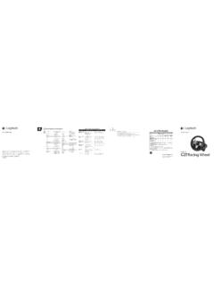
1 X52 PROFESSIONAL HOTAS. USER GUIDE / GUIDE D'UTILISATION. English.. 3 Espa ol .. 41. Fran ais.. 22 Portugu s..60. LOGITECH G X52 PROFESSIONAL SPACE/FLIGHT HOTAS - PRODUCT TOUR. ENGLISH. JOYSTICK. 2-Stage metal trigger Destroy the enemy with the aid of a precise and durable, cool- 3 toggle switches Spring touch trigger. Two-stages can loaded and conveniently be programmed with separate positioned on the base for fire functions. an extra 6 programmable flight commands. 5-position adjustment Missile Launcher to suit all Flip up the spring-loaded hand sizes.
2 Safety cover to activate missile launches. Mode selector switch 3-position rotary Cool-touch metal switch with tristate pinkie switch LED to indicate can be assigned program mode. shift functionality to double up on 2 x 8-way hat programmable switches -1 pre- 3 Fire Buttons Backlit commands. defined as point buttons conveniently of view; select positioned on joystick from multiple view head for instant perspectives and access in the heat assign frequently of the battle. used commands. 3D Rudder Twist handle on GENERAL FEATURES BACKLIGHTING.
3 Joystick for precise rudder control; includes integrated Illuminated buttons and Multi-Function Display rudder lock mechanism. (MFD) - ideal for low light environments, guaranteed to stand out from the crowd. Adjust brightness via Windows control panel. Precision centering mechanism Non-contact technology on x METAL PARTS. and y axes and constant spring force reduce free play, improve Part metal construction for increased control and increase durability. durability and maximum comfort during extended gameplay. 3. THROTTLE.
4 2 Fire Buttons Multi-Function Display (MFD) screen Conveniently positioned indicates: on throttle head for instant access in the Mode and shift state heat of the battle. Mode state is determined by mode selector on the head of the stick. User defined Text area - indicates name of command assigned to button when activated. - supplies name of profile in use and enables on-the-fly profile selection. Profile can also be changed during gameplay by pressing clutch button and scrolling though available profiles moving the pointof- view hat switch up and down.
5 Move the same button left to clear current profile or right to activate profile. Multi Time Displays Time zone (set origin and destination local times in control panel Formattable date/. month/time Stopwatch for flight time Two rotaries provide axes for pitch, trim and yaw settings. Left mouse button. Clutch (I) Button Initiates 'safe mode' to allow on-the-fly profile selection, or to display Mouse controller, button functionality on which can also MFD without activating function as a hat commands. Smooth-action thumb switch.)
6 Slider provides axes for 8-way hat switch: Select from multiple view pitch, trim and yaw perspectives and assign frequently used settings or zoom in/. commands. out view. Scroll wheel positioned on rear of throttle for index finger activation; includes built-in button. Progressive throttle control Super smooth action with metal tension adjustment and detents for programming idle (0-20%) and afterburner (80-100%). settings. 4. GETTING STARTED. ENGLISH. In order for this product to function correctly please install the software from MAINTAINING YOUR CONTROLLER SETTINGS.
7 Your Logitech X52 Professional HOTAS is supplied ready for use. However, we want you to use it in the way that suits you best. We've therefore included the facility for you to change various settings on your stick and throttle can, for example, vary the brightness of the LED buttons, check your stick is working correctly or change the way the date is displayed on your Multi-Functional Display (MFD). You change your controller settings in the properties window for your HOTAS. You can access this by opening the Devices and Printers screen in Windows, right-clicking on the X52 and then selecting Game Controllers.
8 In Game Controllers select the X52 Professional HOTAS and then click Properties. The X52 Professional HOTAS properties window consists of five separate tabs. You can view and change various controller settings in each tab. The settings you can change are described in the following sections. 5. Testing your controller 1. Click the Test tab. The controller features that you can test are displayed below. 2. Test each feature as required. The way you do this varies, depending on what the feature does. It may, for example, involve pressing the corresponding button, or turning the corresponding rotary control.
9 6. Maintaining deadzones ENGLISH. You can create deadzones for each range and axis your controller features move in. They reduce interference that may be caused by unintended movements of the flight stick and other controls. For example, you may want to move your stick in the X axis only, but find it difficult to avoid moving it in the Y axis as you do so. You can set up a deadzone in the Y axis so that these minor movements are not detected by the drivers. What is a deadzone? A deadzone is a part of the range in which an axis moves that is not detected by the drivers and so has no effect on the game in progress.
10 It may be around the center point of the range, or at either end. 7. To maintain your deadzones 1. Click the Deadzone tab. The controls you can create deadzones for are shown, as follows: Each axis is represented by a white box that contains a red line that represents where the control is currently sitting. Moving the corresponding control moves the red line. Use this line to determine exactly where your deadzone must begin and end. Beneath each box is a sliding scale. You use this to specify the size of each deadzone.