Transcription of User Guide - Select Engineered Systems
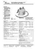
1 User Guide Select Entry Systems Sept. 09 RHRFSPWV3 GENERAL INFORMATION The RHRFSPW ( ) is a 54-bit rolling-code radio receiver for connection to an access con-trol system. The code received is decrypted, then sent to the Wiegand data output terminals, where it can be read from a card reader. TECHNICAL SPECIFICATIONS Power supply : 12 Volts DC Power consumption : 30mA Receiver type : Super-heterodyne Reception frequency : MHz Frequency stability : +- 180 PPM Receiver sensitivity : < uV Code received : 54 bits rolling code Operating temperature : -15C to +55C Dimensions : x Weight : oz Output format : Wiegand RADIO RECEIVER RHRFSPWV3 LED displays when it reads signal from transmitter. 12 12 Volts DC COM Common for Power & Data D1 Wiegand Data 1 D0 Wiegand Data 0 WARNING: Wire attached to Antenna is a specific wave-length. Bending or moving it, WILL result in reduced or poor reception.
2 Follow antenna outline printed on pcb to repair. Where greater signal or range is desirable, refer to the (optional) external antenna kit documentation. P/N RHRFSPANT433 RHRFSPWV3 Connection Definitions 12 VDC COM D0 D1 Button 4 enable jumper. Button 3 enable jumper. Button 2 enable jumper. Button 1 enable jumper. Button 1 Button 2 Button 1 2 2 Button Transmitter RTSPX2 4 Button Transmitter RTSXP4 2 Button Transmitter RTSP2 (Older style) 1 Button Transmitter RTSPX1 Button 1 BUTTON CONFIGURATION: The button Select jumpers enable the transmitter button. The left (or upper) button on the transmitter is button 1 and the right (or lower) button on the transmitter is button 2. If both button enable jumpers 1 & 2 are installed, then either button will produce an output. Button Select jumpers 3 & 4 are used with the RTSXP4 (4 button) transmitter.
3 (See transmitter pictures below.) Antenna RHRFSPWV3 RADIO RECEIVER READER CONNECTIONS Data 0 Data 1 Common 12 VDC 12 VDC Data 1 Data 0 Common 12 VDC Data 1 Data 0 Common 12 VDC Data 1 Data 0 Common This diagram shows the connections from the to various SES card reader modules found in the CAT and TEC series access control units. The RFRHSPWV3 can also be connected to the card reader input on the SG3 DMR, for people who require a 2nd RF receiver (one is already built-in to SG3 DMRs) to control the 2nd relay, using discrete buttons on the RTSXP2 transmitters. Belden 9940 cabling, 500 feet maximum dis-tance. Cut and tape shield at receiver end. Ground shield at card reader end to earth ground stud in back box. Belden 9940 shielded cable 12 VDC = Red Belden 9940 Common = Black Color code Data 1 = White Data 0 = Green Inc Ver. CS. 9E94 (Older style, superseded by above reader module.)
4 2 Reader module. 4 Reader module. Select Engineered Systems , Inc. 7991 West 26th Avenue Hialeah, Florida 33016 Phone: 09/09 RHRFSPWV3