Transcription of Using Automatic Exposure Control in Digital Radiography
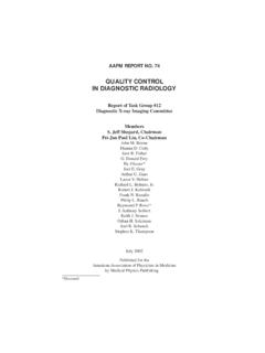
1 1 Using Automatic Using Automatic Exposure Control in Exposure Control in Digital RadiographyDigital RadiographyA. Kyle Jones, Kyle Jones, M. D. Anderson Cancer M. D. Anderson Cancer CenterDepartment of imaging PhysicsDepartment of imaging Physics2008 AAPM Meeting, Houston, TX2008 AAPM Meeting, Houston, TXAutomatic Exposure ControlAutomatic Exposure Control The purpose of AEC is to deliver consistent, The purpose of AEC is to deliver consistent, reproducible exposures across a wide range of reproducible exposures across a wide range of anatomical thicknesses, tube potentials, and anatomical thicknesses, tube potentials, and usersusers Detectors used in AEC systems include Detectors used in AEC systems include fluorescent screens with fluorescent screens with PMTsPMTs/photodiodes, /photodiodes, ionization chambers.
2 And possibly solid state ionization chambers, and possibly solid state detectorsdetectorsAEC system DiagramAEC system DiagramGeneratorAEC ControllerAmplifierReference Voltage-3 -2 -1 0 +1 +2 +3kVpComparatorBackupTerminate?Loosely based on Bushberg, Seibert, Leidholdt, and Boone, The Essential Physics of Medical AEC performance Fundamental AEC performance characteristicscharacteristics Initial acceptance testingInitial acceptance testing Sensor selector/locationSensor selector/location Density correctionDensity correction Screen sensitivity adjustmentScreen sensitivity adjustment Sensitivity vs. speed settingSensitivity vs. speed setting ReproducibilityReproducibility AEC balance/field sensitivity matchingAEC balance/field sensitivity matching AEC sensitivityAEC sensitivity Patient thickness trackingPatient thickness tracking kVp trackingkVp tracking Beam quality correction curveBeam quality correction curve Backup timerBackup timer Cell mappingCell mapping Minimal Exposure durationMinimal Exposure duration Field size tracking*Field size tracking* Ongoing QC testingOngoing QC testing AEC sensitivityAEC sensitivity Density correctionDensity correction kVp trackingkVp tracking Patient thickness trackingPatient thickness tracking ReproducibilityReproducibility AEC balanceAEC balance Backup timerBackup
3 Timer Minimum Exposure durationMinimum Exposure duration Field size tracking*Field size tracking*Remember thisRemember this Test your system at the SID for which the grid is Test your system at the SID for which the grid is focused and your system calibratedfocused and your system calibrated AEC detectors themselves have an inherent AEC detectors themselves have an inherent energy dependenceenergy dependence Slight variations do exist between cells and Slight variations do exist between cells and should be evaluated upon acceptance testingshould be evaluated upon acceptance testingTrue vignette: Siemens Sireskop system with reciprocating grid. AEC balance consistently failed when tested at an SID of 100 cm.
4 Moving the tube to an SID of 115 cm resulted in passing test. Cause: Grid reciprocation delay was set to result in appropriately exposed images at an SID of 115 cm, where Siemens calibrates. We were able to adjust the delay to balance the AEC cells within 10% and provide acceptable image quality at 100 cm t +RCUnit differences existcell differences existDensity controlDensity Control Adjusts mAs upward or downward in increments of 25 Adjusts mAs upward or downward in increments of 25--30% per step30% per step Some newer DR systems do not incorporate this Some newer DR systems do not incorporate this featurefeature Published guidelines/recommendationsPublished guidelines/recommendations Tested for proper operation and similar step size (NCRP 99)Tested for proper operation and similar step size (NCRP 99) to OD per step (AAPM 74) to OD per step (AAPM 74)
5 44--step controller should adjust by 20step controller should adjust by 20--25% per step (AAPM 25% per step (AAPM 14)14) Fundamental differences from S/F: Absence of feature Fundamental differences from S/F: Absence of feature on some systemson some systems Curious that some systems still include this featureCurious that some systems still include this featureAir Air kermakermavs. sensitivity selectionvs. sensitivity selection Many DR systems feature selectable Many DR systems feature selectable sensitivitysensitivity settings settings for imaging protocolsfor imaging protocols Refers to AEC, not Digital detectorRefers to AEC, not Digital detector These settings adjust the sensitivity of the AEC cells These settings adjust the sensitivity of the AEC cells resulting in higher or lower image receptor exposuresresulting in higher or lower image receptor exposures Akin to Using different speed screen/film combinations for Akin to Using different speed screen/film combinations for different body regions different body regions 200 speed for chest and 400 200 speed for chest and 400 speed for generalspeed for general While no regulations or guidelines exist, it is prudent to While no regulations or guidelines exist.
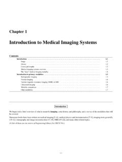
6 It is prudent to verify that Exposure varies logically and predictably with verify that Exposure varies logically and predictably with selectionselection Inversely proportionalInversely proportionalAir Air kermakermavs. sensitivityvs. sensitivity Fundamental differences from S/F: Similar to Fundamental differences from S/F: Similar to screen selector settingscreen selector setting Philips DR system Philips DR system Phil RauchPhil Rauch Resolution of EI is not sufficient to identify changes Resolution of EI is not sufficient to identify changes in sensitivity settingin sensitivity setting051015202530350200400600800100012 00140016001800 Sensitivity mAsSS= SNR vs. Sensitivity BalanceAEC Balance Field sensitivity matchingField sensitivity matching To achieve consistent exposures, AEC cells To achieve consistent exposures, AEC cells should be balancedshould be balanced Manufacturers of xManufacturers of x--ray systems use several ray systems use several different schemes for AEC balancingdifferent schemes for AEC balancing Thus, a oneThus, a one--sizesize--fitsfits--all test will not be valid if all test will not be valid if you work with a variety of systemsyou work with a variety of systems Fundamental difference from S/F: Some Fundamental difference from S/F.
7 Some manufacturers have changed schemesmanufacturers have changed AEC balance schemesCommon AEC balance schemesAEC BalanceAEC Balance Test AEC balance during acceptance testing to set a baseline Test AEC balance during acceptance testing to set a baseline standard for balancestandard for balance Ask your service engineer about the calibration/balancing Ask your service engineer about the calibration/balancing procedureprocedure Many manufacturers today use AEC systems that are not serviceablMany manufacturers today use AEC systems that are not serviceable for e for balance balance they can only be replacedthey can only be replaced In this case you are stuck with manufacturerIn this case you are stuck with manufacturer s balance schemes balance scheme Other manufacturers still have tunable AEC cellsOther manufacturers still have tunable AEC cells Pots in generatorPots in generator Software interfaceSoftware interface Pots in detector housingPots in detector housing Published guidelines/recommendationsPublished guidelines/recommendations 5% across all combinations (AAPM 14)5% across all combinations (AAPM 14)
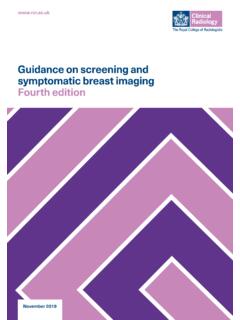
8 AEC BalanceAEC Balance Cells must also be matched when used in combinationsCells must also be matched when used in combinations AEC systems may terminate the Exposure when the most AEC systems may terminate the Exposure when the most sensitive cell reaches the required current level, or may averagsensitive cell reaches the required current level, or may average e the signal between the cells being usedthe signal between the cells being used Same criteria applySame criteria 2 Unit +CR+ 3 Unit 1 Unit 1 AllAllL+CL+CL+RL+RRRLLCCSee also X-ray generator and Automatic Exposure Control device acceptance testing by Raymond P. Rossi, , in Specification, Acceptance Testing and Quality Control of Diagnostic X-ray imaging Equipment, Proceedings of the 1991 AAPM Summer SchoolBackup timerBackup timer In the case of a system In the case of a system malfunction or technical malfunction or technical error, the Exposure must be error, the Exposure must be terminated after a certain terminated after a certain period of time or delivered period of time or delivered mAsmAs 600 mAs 600 mAs 51 kVp51 kVp 2,000 mAs < 51 kVp2.
9 000 mAs < 51 kVp 21 CFR102021 CFR1020 Many Digital Radiography Many Digital Radiography systems have preset time systems have preset time limits based on kVp and mA limits based on kVp and mA settings, and some will settings, and some will terminate if no signal is terminate if no signal is detecteddetectedReproducibilityReproduci bility KKaadelivered by the AEC system should be delivered by the AEC system should be reproduciblereproducible Published guidelines/recommendationsPublished guidelines/recommendations COV < (AAPM 14)COV < (AAPM 14) 5% of average (NCRP 99)5% of average (NCRP 99) II ll leave it as an exercise to prove that these ll leave it as an exercise to prove that these guidelines do not say the same thingguidelines do not say the same thing4 Minimum Exposure durationMinimum Exposure duration Thin or less dense body parts can lead to very Thin or less dense body parts can lead to very short Exposure times for AECshort Exposure times for AEC--controlled controlled radiographyradiography chest imaging , small chest imaging .
10 Small patients AEC systems should be capable of delivering AEC systems should be capable of delivering appropriate exposures at these Exposure timesappropriate exposures at these Exposure times Published guidelines/recommendationsPublished guidelines/recommendations TTminmin< 1/60 sec or 5 mAs, whichever is greater < 1/60 sec or 5 mAs, whichever is greater (21 CFR1020)(21 CFR1020)Minimum Exposure duration Minimum Exposure duration --DRDR However, for DR systems, some of which require less Exposure thaHowever, for DR systems, some of which require less Exposure than n film/screen systems, this limit is insufficientfilm/screen systems, this limit is insufficient Typical PA chest xTypical PA chest x--ray at 125 kVp and 320 mA: 3ray at 125 kVp and 320 mA: 3--4 ms4 ms Most measurement equipment is