Transcription of UVM Harness Whitepaper - Synapse Design
1 A proven methodology to hierarchically reuse interface connections from the block to the chip level UVM. Harness Whitepaper The missing link in interface connectivity. By David Larson, Director of Corporate Verification Revision August 4, 2011. Table of Contents Introduction .. 2. What is a Harness ?.. 3. Interface Binding .. 3. The Other End .. 4. A Complete 4. Connecting the Harness .. 6. Connecting Harnesses in System Simulations .. 6. Virtual Harnesses .. 6. Advanced Interfaces .. 7. Arrays of interfaces .. 7. Scalable interfaces .. 8. Summary .. 9. Thanks .. 9.
2 UVM Harness , David Larson Page 1. Introduction In every UVM test bench, System Verilog interfaces must be used to connect signals from the RTL to the test environment. For a single block-level test bench, the interface connections are typically made by connecting each signal in an interface to the ports of the DUT, like this: module top;. wire clk, reset_n;. my_signals ifc(clk, reset_n); // instantiate the interface switch DUT (..clk(clk), .reset(reset_n), .data( ), // connect each signal of the interface to ports on the DUT..status( ), .port0( [0]), .port1( [1]).)
3 ;. initial begin uvm_config_db#(virtual my_signals)::set(null, " *", "vif", ifc);. end endmodule This approach is fine for simple, single-use block level test but it falls apart for multi-block test benches for several reasons: 1. The connections are not reusable. You must reconnect each signal on every block to your interfaces in a system test bench. This task becomes more ominous when there are many modules that need to be reconnected and each of those modules has several interfaces and each of those interfaces has many signals. Connecting the interfaces can be a major task.
4 2. The ports may not be available. In synthesizable netlists, interfaces often aren't used to connect the modules together because of tool (or corporate) limitations. Instead, wires are typically used to stitch the modules together. You could try to assign your interface signals to the wires, but it is very difficult to get the directions right and very easy to make a mistake (believe me, I've tried). You could easily get lost floating on an ocean of tedious signal connections. A better approach is to use a reusable Harness . With a Harness , the connections made in a block-level test bench can be reused in multi-block test benches.
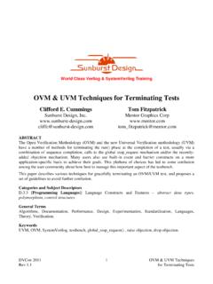
5 Also, a collection of harnesses can be grouped together into virtual (or system) harnesses that connect system-level environments to yet larger system environments. UVM Harness , David Larson Page 2. What is a Harness ? Like a car stereo Harness , a UVM Harness is a collection of wires (grouped together in interfaces) with at least two ends or connectors to it. One end connects to the module(s) and the other end connects to the UVM environment. The connectors in the Harness are written for your module and environment. Once the Harness is created, you can then use it in all of your block-level and system-level test benches.
6 All you have to do is snap in the connectors. Figure 1 - A car stereo Harness . A connector on one Fundamentally, a connector is an interface that is bound end snaps into your specific stereo; the other connectors snap into the wiring for your specific car. to your module. Once the interfaces are bound, you never have to connect that end of the Harness again. Interface Binding System Verilog allows you to bind (or add) some of your own items to modules from a separate file . allowing you to amend the definition of the module. This mechanism is sort of like aspect-oriented programming.
7 It is intended to be used in the test bench to add things like coverage, assertions, monitors, interfaces1. When you bind an interface to a module, the compiler acts as if that the interface is instantiated inside the module. This also means that you can access signals and ports as if the context of your code is inside the module as well. So, referring to internal signals and ports from an external file like this is perfectly valid: bind math_coprocessor_module reg_ifc regIfc(.clk(clk), .reset_n(reset_n), .address(addr), .data(data), .wr(write), .req(request), .ack(ack)).
8 Where the signals clk, reset_n, addr, data, write, request and ack are ports of a module (as seen from the inside of the module) called the math_coprocessor_module2. Notice that all of the interface signals are declared as ports of the interface, which allows you to connect all of the signals in the interface instantiation and bidirectionally when necessary. Also notice that since we are connecting the interface to the port names of the module, the connections are always valid for every instance of this module. Binding the signal interfaces creates one end of the UVM Harness .
9 Now we need to create the other end of the Harness that connects to the 1. See the Verilog LRM IEEE 1800-2009, section Binding auxiliary code to scopes or instances . 2. System Verilog also allows you to bind to a particular instance of a module, though it is generally best to bind to the module itself, so that the interface instantiations are automatically added to every instance of the module in the hierarchy. UVM Harness , David Larson Page 3. The Other End The other end of the Harness is a function that will connect the interfaces to the UVM environment. We do this by adding a set_vifs() function to the module.
10 The problem is that System Verilog does not allow you to directly bind functions to a module. You can, however, put that function in a dummy interface and then bind that interface to the module (we'll go over other uses of this dummy interface later): interface math_coprocesser_harness(); // the dummy interface function void set_vifs(string path);. uvm_config_db#(virtual reg_ifc)::set(null, {path,".reg_agent.*"}3, "vif", );4. uvm_config_db#(virtual cmd_ifc)::set(null, {path,".cmd_agent.*"}, "vif", );. uvm_config_db#(virtual usb_ifc)::set(null, {path,".usb_agent.*"}, "vif", ).