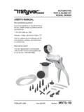
Transcription of VACUUM BRAKE BLEEDER MODEL MV6830 - Mityvac
1 SPECIFICATIONSR eservoir Capacity: quarts ( liters)Bleed Tube Length: 72 in. (1830 cm)Evac Tube Length: 48 in. (1220 cm)Working Pressure: 60 to 150 psi ( to bar)Air Consumption: scfm @ 90 psi ( l/s @ bar) VACUUM @ 30 psi ( bar): in. hg (22 kpa)@ 60 psi ( bar): in. hg (56 kpa)@90 psi ( bar): in. hg (90 kpa)@150 psi ( bar): 27 in. hg (91 kpa)Fill Rate@ 30 psi ( bar): oz/min (725 ml/min.)@ 60 psi ( bar): oz/min (1460 ml/min.)@90 psi ( bar): oz/min (2095 ml/min.)@150 psi ( bar): oz/min (2095 ml/min.)PageSection- MV26- 1 BForm 822844 APRIL - 2005 VACUUM BRAKE BLEEDERMODEL MV6830 USER S MANUALHave Technical Questions?If you have questions, or require technical service, please contact our trained service technicians at:1-314-679-4200 ext.
2 4782 Monday - Friday 7:30 am to 4:15 pm CSTV isit our website at for new products, catalogs and instructions for product Service Parts?To order replacement or service parts, visit us online at or call toll free Number - 2 Form 822844 BRAKE BLEEDERKIT ItemPart No. DescriptionItemPart No. Description1822664 BRAKE BLEEDING ADAPTER8822705O-RING KIT2822694 BLEEDING TUBE KIT9822706 RESERVOIR GASKET KIT3822700 VALVE KIT10822709 MUFFLER KIT4822701 BASE KIT11822722 SUCTION TUBE KIT5822702 COUPLER SWIVEL KIT12822731 FLOAT KIT6822703 COUPLER KIT13822753 HOOK KIT7822704 VENT KIT14 MVA6825 FLUID REFILL KIT15 822842 RESERVOIR Indicates changePage Number - 3 Form 822844 Important Precautions Always read carefully and understand instruc-tions prior to using this equipment BRAKE fluid is highly corrosive.
3 Wear gloves and approved safety goggles at all times, and pre-vent contact of the fluid with painted surfaces. Consult and follow the vehicle manufacturer s recommended procedures when servicing any hydraulic system. Do not use this unit with flammable liquids or with fluids at temperatures above 175 Fahren-heit (80 Celsius). Properly dispose of old fluids, and replenish hy-draulic systems with new BRAKE fluid from freshly opened containers. Do not attempt to pressurize the BLEEDER /evacu-ator. It is designed for VACUUM use only. This unit is equipped with an automatic shut-off device that will prevent fluid from entering the compressed air stream and ejecting through the exhaust.
4 However, if the unit is continuously op-erated when the reservoir is full, residual pres-sure will allow the reservoir to completely fill with fluid, creating the potential for spillage when the lid is removed. To prevent this situation, empty or turn the unit off prior to filling the reservoir completely full. The screws included in Base Kit 822701 are provided to secure the base to a work surface. Do not use the screws to attach the base to the of OperationThis unit is designed for use as a VACUUM BRAKE or clutch BLEEDER , or fluid evacuator. It utilizes com-pressed air between 60 psi ( bar)and 150 psi ( bar), and a venturi system, to build VACUUM in the reservoir. By attaching the proper accessory to the coupler located on the top of the unit, the VACUUM can be used to drain BRAKE fluid from a hy-draulic system such as the BRAKE or clutch systems on an automobile.
5 It can also be used to evacu-ate a variety of fluids from reservoirs including the master cylinder or those for power steering fluid or engine automatic master cylinder refill kit is included with this unit. It is conveniently designed for use with a standard bottle of BRAKE fluid, to maintain an adequate fluid level in the master cylinder while the hydraulic system is bled. Instructions are included with the kit for its use. Instructions for Bleeding BrakesIMPORTANT: This unit is designed for servicing a variety of vehicles in a safe, convenient manner. However, options such as load sensors or anti-lock brakes, available on many automobiles, may require additional steps or equipment to perform a proper service job.
6 The procedures below are to serve as guidelines for the use of this equipment, in addition to these guidelines, always follow the manufacturer s recommended procedures when servicing each unique old fluid from the BRAKE mas-ter cylinder1. Properly park the vehicle on level ground and turn the engine Clean the exterior of the master cylinder and master cylinder cap to prevent dirt from entering the master cylinder when the cap is Remove the cap from the master cylinder Connect clean, regulated (60 psi ( bar) to 150 psi ( bar)) compressed air to the male quick disconnect nipple attached to the swivel air inlet, located on one end of the VACUUM BLEEDER Connect the appropriate end of the evac tube assembly to the female quick disconnect cou-pler located on top of the VACUUM Insert the other end of the evac tube assembly into the master cylinder fluid reservoir, and push the VACUUM BLEEDER throttle forward to start the VACUUM (allow a few seconds for VACUUM to build in the BLEEDER reservoir before suction oc-curs).
7 While evacuating the old fluid, stir it up to break loose and remove any sludge that has ac-cumulated on the bottom and walls of the master Once all fluid is removed, turn off the BLEEDER and refill the master cylinder with new manufac-turer s recommended BRAKE fluid. Indicates change Page Number - 4 Form 822844 VACUUM bleed BRAKE lines and wheel BRAKE cylindersNote: Prior to bleeding, ensure the master cylinder is full of new manufacture s recommended BRAKE fluid. An automatic master cylinder refill kit is included with the VACUUM BLEEDER to maintain the level of new fluid in the master cylinder during the BRAKE bleeding process. Follow the instructions in-cluded with the kit to prevent air from being sucked into the master cylinder pistons, BRAKE lines, and wheel cylinders while bleeding the brakes.
8 Addi-tional automatic refill kits are available from Properly position the vehicle for safe convenient access to the BRAKE bleed screw located on each wheel BRAKE Make sure that all bleed screws are Connect clean, regulated (60 psi ( bar) to 150 psi ( )) compressed air to the male quick disconnect nipple attached to the swivel air inlet, located on one end of the VACUUM BLEEDER Connect the appropriate end of the bleed tube assembly to the female quick disconnect cou-pler located on top of the VACUUM BLEEDER . Note: Consult the vehicle manufacturer s guide-lines for the proper wheel bleeding sequence and VACUUM bleeding Slip the bleed screw adapter located on the op-posite end of the bleed tube assembly, over the nipple of the bleed Operate the VACUUM BLEEDER by pushing the throttle forward (allow a few seconds for vacu-um to build in the BLEEDER reservoir before suc-tion occurs), and with the appropriate wrench, loosen/open the bleed screw slightly, until fluid is visibly draining through the bleed hose and into the reservoir.
9 Note: During the bleeding process, as BRAKE fluid is being vacuumed through the bleed screw, air will also be sucked into the bleed tube from around the bleed screw threads. This can give the misconception that air is bleeding from the lines, however it is normal and does not indicate a malfunction. To prevent or reduce this introduction of air, coat the bleed screw threads with silicon grease prior to Keep the bleed screw open until new fluid is visibly flowing through the bleed tube (typically 20 to 30 seconds).8. Close the bleed screw firmly, without over tight-ening, prior to removing the bleed screw adapter or shutting off the BLEEDER . Note: It is important to ensure that the bleed screw adapter remains connected to the bleed screw, and the BLEEDER is still pulling a VACUUM while the bleed screw is closed.
10 This prevents air from being sucked back into the wheel cylin-der from around the bleed screw threads, before the bleed screw is tightened and sealed. Note: If an automatic refiller such as the one provided with this unit, is not used, be sure to periodically check the level and top off the BRAKE fluid in the master for bleeding hydraulic clutch systemIMPORTANT: This unit is designed for servicing a variety of vehicles in a safe, convenient manner. However, hydraulic clutch systems vary between vehicles, in design, in components, and even the location and design of the bleed screw. Due to these differences, the following procedures are to serve only as a guideline for the use of this equip-ment.