Example: bankruptcy
Vacuum Circuit Breakers - Fuji Electric
④ Installation Type Symbol Fixed type P Draw-out type for HS2530 M Draw-out unit type for class CW X, U Draw-out unit type Y for class MW or PW ⑤ Normal current Rated [A] Symbol 600, 630 06 1200, 1250 12 2000 20 3000 30 4000 40 ⑥ Closing system* System Symbol Motor-spring stored-energy M (rapid auto-reclosing) ⑦ Tripping system* System ...
Tags:
Information
Domain:
Source:
Link to this page:
Documents from same domain

Kawerau and Nga Awa Purua Geothermal Power …
www.fujielectric.comKawerau and Nga Awa Purua Geothermal Power Station Projects, New Zealand 83 tor, purifier and steam-line scrubbing system. The two-phase fluid gathering system results in relatively

Packaging Technologies for SiC Power Modules
www.fujielectric.comPackaging Technologies for SiC Power Modules 77 issue: Power Semiconductor contributing in energy and environment region 2.4 High reliability Improved reliability at high temperature is need-

Contactors and Starters - fujielectric.com
www.fujielectric.comContactors and Starters AC operated magnetic contactors Type Specification 3-phase squirrel-cage motor capacity (AC3)*1 Magnetic contactor Combined thermal

Fly-back transformer design instructions Design tool
www.fujielectric.comFly-back transformer design ... the transformer for Fly-back type power supply. ... used by using the output power described in the catalog as a guide.

New Products Modified Products - fujielectric.com
www.fujielectric.com4 FUJI ED & C TIMES Vol. 7 Earth leakage circuit breakers IEC and CE marking conformed • Line protection Series SG series EG series Ampere frame 30

Phase Segregated Type SF6 Gas Insulated …
www.fujielectric.comClosed position Puffer cylinder Arcing contact Arcing contact Moving contact support Moving contact Nozzle Fixed contact SF 6 gas in the puffer cylinder is …
New Products Modified Products - fujielectric.com
www.fujielectric.comFUJI ED & C TIMES Vol. 13 6 MCCBs and ELCBs G-TWIN series A new compact high-performance MCCB and ELCB series – G-TWIN

Direct Liquid Cooling IGBT Module for Automotive …
www.fujielectric.comDirect Liquid Cooling IGBT Module for Automotive Applications 57 issue: Power Semiconductor contributing in energy and environment region nesses of several tens of μm, and was unable to con-

Chapter 4 Troubleshooting - Fuji Electric
www.fujielectric.comChapter 4 Troubleshooting 4-3 External abnormalities Cause Device failure mode Further checkpoints Gate overvoltage Static electricity Spike voltage due to excessive length of gate wiring Avalanche Overvoltage Check operating conditions (anti-static protection). Check gate voltage. Overheating Loose terminal screw or cooling fan shut down

Chapter 5 Protection Circuit Design
www.fujielectric.comprotective circuit built in, thereby simplifying the drive circuit design. For more details, refer to Chapter 7 “Drive Circuit Design”. Fig. 5-4 shows an IGBT waveform during short circuit protection. + +
Related documents

RA 0400 C, RA 0502 C, RA 0630 C - Busch Vacuum Solutions
www.buschvacuum.comIf the vacuum pump is used as part of a vacuum system: • Busch recommends the installation of an isolation valve in order to prevent the oil from flowing back to the vacuum system. • Do not use the anti-suck-back valve as a system check valve. NOTICE Do not fill oil through the vacuum pump inlet. Risk of damage to the vacuum pump!

APCO AIR VALVE GUIDE - DeZURIK, Inc.
www.dezurik.comAir/Vacuum Valve Series 150 Combination Air Valve Series 140C Sewage Air/Vacuum Valve Series 401 ... installation of ARV’s at the high points will remove the restrictive pockets of air to restore system efficiency. ... lower system pressure, a larger diameter orifice can be used to release accumulated air.
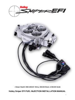
Holley Sniper EFI FUEL INJECTION INSTALLATION MANUAL
documents.holley.comApr 30, 2018 · set screw in 2-3 places. The installation of this set screw is critical to system operation. Failure to do so will cause false MAP sensor readings. THROTTLE BODY INSTALLATION 1. Start by labeling all vacuum lines for easy identification, i.e. brake booster & vac advance for distributor. If any lines appear damaged, now is the time to replace them.

CHAPTER 13 Health Care Facilities and MEDICAL GAS ... - …
www.oregon.govprotected by a vacuum breaker or equivalent backflow protection device in accordance with Section 603.0. Part II – Medical Gas and Vacuum Systems. 1309.0 Application. 1309.1 The provisions herein shall apply to the installation and testing of medical gas and vacuum piping in hospitals, clinics, and other health care facilities.

5.1 Cryogenic system design - Fermilab
uspas.fnal.govfor ease of installation in less stringent operating conditions. Perlite is a commercial powder of random size and shape (cheap) Hollow glass micro-spheres (3M) of 50 to 200 µm in diameter Vacuum requirements are less critical. Good performance at p ~ 0.1 Torr compared to 10-4 torr for MLI Perlite is mostly used for less

DESIGNING STEAM JET VACUUM SYSTEMS - graham …
www.graham-mfg.comVacuum piping.Paragraph 6.3 of the Heat Exchange Institute’s Standards for Steam Jet Vacuum Systems (4th ed.) details the pro-cedure for calculating pressure drop in vacuum systems. In general, the diameter of the piping between the process and the ejector system must be at least as large as the suction connection in the first-stage ejector.

Installation, Inspection, Maintenance, and Repair …
www-group.slac.stanford.eduInstallation, Inspection, Maintenance, and Repair Requirements . ... 2.2.4 Leak Test and Mechanical Integrity for Vacuum Systems . A vacuum system/vacuum component must be leak tested to determine conformance with the maximum permissible leak specified on the drawing, purchase order, or other documents supplied at the order. ...

INSTALLATION MANUAL FOR VERTICAL WELL SYSTEM TANKS
images.thdstatic.comsafety of the system. c.you have a deep well submersible pump, remove all the air If charging devices from the well system (snifter valves, bleeder orifices, vacuum lines and connection). Then plug the holes . where these devices were located (see your owner’s manual for location of these devices). These devices are not needed for

INSTALLATION TUNING AND TROUBLESHOOTING MANUAL
documents.holley.comMar 28, 2000 · 8.0 PRO-JECTION SYSTEM INSTALLATION ... 40 5/16" Vacuum Line 1 N/A 41 Fuel Pump wiring Harness 1 N/A TBI Service Parts: Air Charge Temperature Sensor 1 534-46 Fuel Injector 650 CFM 4 522-27 Fuel Injector 700 CFM 4 522-74 Fuel Injector 900 CFM 4 522-26 Fuel Pressure Regulator Diaphragm 1 512-1 ...