Transcription of Valve Failure Clues - Read ‘Em and Weep - sbintl.com
1 1 Valve Failure Clues : read Em and Weep By Ted Tunnecliffe engine Builder Magazine, August 2001 Valve failures come in all sizes, shapes and types. If you just look at them then sit back and do nothing they ll be back. So what should you do? Well, probably the most important thing is to understand why they happen. Then, maybe you ll be able to avoid them the next time around. We ve spent most of our adult lives looking at broken valves , and I don t believe anyone can explain the reasons for them all; I know I can t. Sometimes all you have to look at is a beat up chunk of steel that has been battered by the piston to the point where you can t even tell it was a Valve . Something I have learned over the years is that sometimes you can get a clue by looking at other areas of that beat-up chunk. Operating History A very important aspect of Valve Failure analysis is to understand the operational history. However, sometimes that is easier said than done. Whoever gives it to you may not know the details himself.
2 In the past, we ve dealt with companies that made both spark-ignited (gasoline, LPG, CNG, sewer gas, etc.) and compression-ignited engines (diesels, both direct and indirect injected varieties). So, right up front we need to know the combustion method or we won t have a prayer of finding an answer. Other questions to ask include: What kind of load was the engine under? Was it light, medium or heavy duty? Is there anything known about the characteristic operation temperatures of the valves ? Any information on peak combustion pressures or air/fuel ratios? Cylinder-to-cylinder Valve temperature variation? Were there any other Clues about the operation that would help? What type of fuel was used? If it is a diesel, what grade of fuel? (Some companies pride themselves on being able to burn anything you can pump). Did the fuel contain a lot of sulfur or other contaminants? Especially in spark-ignited engines, was oil consumption a possible factor?
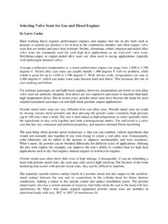
3 If it is a gaseous fuel, what type and how clean was it? And how about the air? If it was running on the desert, ingested sand or very high temperatures could be concerns. Was there any history of similar Valve failures? If you re going to be of any help in such analysis, you need to get as much information as you can even though you may not use most of it. 2 Valve Contact Marks Wherever the Valve has been in contact with another part or surface, there is usually a mark left by that contact. That would normally include the keeper groove area, the tip surface, the stem and the seat face. Valve Tip Surface Valve activation is normally the result of action by some sort of opening method like a rocker pad or similar component. Such parts frequently leave witness marks behind, and that is what we are looking for. On a Valve tip, that mark may be vague concentric circles of varying diameters as in Figure 1. Although push-rod Valve activation systems typically cause valves to rotate during operation to a greater degree because of their lower natural frequency than direct acting systems, the rate of rotation, and even if the valves rotate at all, is not a given.
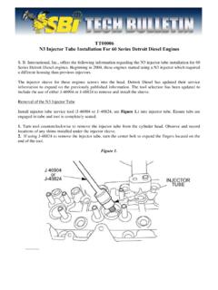
4 The photo in Figure 2 is an example of the contact patterns on a Valve that did not rotate in a push rod engine . You might also see a "bow tie" pattern where only two such rocker pad patterns are visible. Another thing that you should look for is tip wear. Since the overall length of a Valve is not typically defined it is usually a function of the total of other length characteristics you can t simply measure the length and know if the tip wore some small amount. What I usually do is to look at the tip chamfer. Since a chamfer should be there in most cases, you can at least estimate the amount of wear. You won t know how much, but you will know if some wear has taken place; that fact in a Failure analysis may be of some help. Near the key groove or grooves, an important thing to look for is "chafing;" in other words, key movement during operation.
5 The normal pattern should be a couple of irregularly roundish marks showing where the high points of each of the keys were in contact with the Valve stem. If Valve gear separation has taken place, you will usually see a pattern that indicates circumferential movement of the keys. Valve gear separation means that you can forget about the Valve using that nice seating ramp that was designed into the cam. Instead it may hit the cylinder head seat at flank velocity and most likely take the head of the Valve off very quickly. Figure 2: Example of contact pattern on Valve tip indicating that the Valve has oscillated instead of rotated against the rocker pad. Figure 1: Example of the circular concentric contact marks indicating that the Valve has rotated against the rocker pad during operation. 3 In two- Valve engines, intake valves because they are of a larger diameter than the mating exhausts are frequently more susceptible than are the exhausts to "float" or "toss" due to their heavier weight.
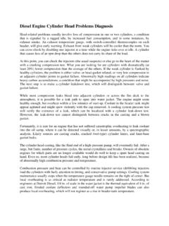
6 They may not fail more quickly, however, because the exhaust may be weaker due to its higher operating temperature. Figure 3 shows an example of a chafed Valve groove area. So what causes this erratic Valve motion? A weak Valve spring, an improperly assembled Valve gear, a Valve stem sticking or, as is frequently the case, engine overspeeding. If the engine is designed to red line at six grand and you run it up to eight, good luck, but don t come crying about your broken valves . Key And Retainer Marks In addition to the contact marks on the Valve itself, if you happen to have the keys and retainers to look at, you can sometimes get some good information from them, too. That is particularly true of the keys. On their , if you can see scuffing and chafing marks they should match those on the Valve .
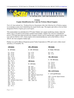
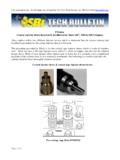
7 Take a look; it may very well confirm your initial analysis. On the keys in Figure 4 we can see the chafing and the match up of it to the chafing on the surface of the retainer. You can put this one to bed. In some instances, especially in heavy-duty engines, "threaded" Valve guides are used. The heavy-duty guys are saddled with the need to run under warranty sometimes for as much as a million miles so they tend to use every trick in the trade to assure long durability. Very strict controls of both the microstructure and the surface finish of the cast iron guides are generally used. They have found that, by running a fast lead tap down the guide prior to finish machining, they can extend the life of both the guide and the Valve . The theory is that the grooves on the guide allow for the retention of any available lubricant. Along these same lines, years ago a controlled roughness of about 50 microns was used on passenger car Valve stems with the same idea in mind.
8 That was before the use of hard chromium, which is now almost standard on such parts, the last we knew. When you examine a Valve returned from the field, look at the stem surface for evidence of its movement within the guide. You should see a pattern at both ends indicating the full range of motion that the Valve had. Figure 3: Chafe marks at the side of the groove indicating that the Valve has been bouncing instead of following the cam Figure 4: Circumferential chafing pattern on both the spring retainer and the Valve keys indicating movement relative to each other during operation, 4 In addition, you may be able to spot the amount of Valve lift from the contact pattern of it starting and stopping. That is not always easy to see, but it may be possible. If you can see it you may be able to confirm the actual lift that really took place as opposed as to what it was supposed to be. (Don t trust anybody!). The photo in Figure 5 shows an example of the patterns we are talking about.
9 Throat Or Underhead Area For the most part, what you can expect to see in this zone of a Valve , if anything at all is present, at least with an exhaust Valve , is corrosion. Especially in these days of good quality fuels, there is usually little indication of distress. passenger car engines are well controlled as a result of fuel injection rather than carburetion, for one thing. Variations in air/fuel ratio from cylinder-to-cylinder in carbureted engines can cause high Valve throat temperatures, especially in the lean cylinders, because the burning is still going on when the Valve opens. You can adjust the runner lengths all you want, but you will still have more variation in the air/fuel ratio of the change from cylinder-to-cylinder, and therefore hotter individual valves than is desirable. Lead in the gasoline and the PbO (lead oxide) deposits on valves and most diesel fuels are equally controlled and are designed and tested to death.
10 That wasn t always true, of course, but now about the only thing we have to show you here is some old stuff. And even in those old days intake valves experienced very few of these problems because they ran so cool. If, by chance, you do see engines that have run on leaded gas you may see the kind of attack in the underside of the Valve head that is shown in Figure 6. Seat Face In an engine that has run a typical durability cycle on a dyno as defined by the manufacturer, the seat faces of the valves usually show nothing distinctive at all. The same would be true of valves that came out of a long term run in the field. You might see patterns where the valves have contacted the cylinder head seat, but typically you will see no significant amount of wear.