Transcription of Variable Axial Piston Pump (A)A10VSO - SophTech Worldwide
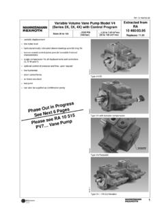
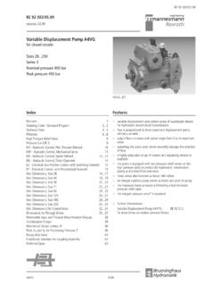
1 IndustrialHydraulicsElectric Drivesand ControlsLinear Motion andAssembly TechnologiesPneumaticsServiceAutomationM obileHydraulicsopen circuitVariable Axial Piston Pump(A)A10 VSORA 92 711 1/36 Replaces: 92 712 18 .. 140 Series 31 Nominal pressure 4000 psi (280 bar)Peak pressure 5100 psi (350 bar)Features Variable displacement Axial Piston pump of swashplatedesign for hydrostatic open circuit systems Flow is proportional to drive speed and displacement. It canbe infinitely varied by adjustment of the swashplate. SAE mounting flange Flange connections to SAE 2 case drain ports Good suction characteristics Permissible continous pressure 4000 psi (280 bar) Low noise level Long service life Axial and radial load of drive shaft possible High power-weight ratio Wide range of controls Short response times Through drive option for multi-circuit systemContentsOrdering code - standard range2 Fluids4 Technical data5 Noise level7 Drive power and flow8DG - two point, direct control10DR - Pressure control12 DRG - Pressure control, remote14 DFR / DFR1 - Pressure flow control16 DFLR - Pressure / flow / power control18 Unit dimensions, Size 1820 Unit dimensions, Size 2821 Unit dimensions, Size 4522 Unit dimensions, Size 7123 Unit dimensions, Size 10024 Unit dimensions.
2 Size 14025 Through drives26 Overview of through drive mounting options27 Dimensions of through drives29 Installation notes34 Safety information352/36 Bosch Rexroth AG | Industrial Hydraulics(A)A10 VSO | RA 92 711 device18284571100 140 Two-position control, direct controlsDG DGPressure controlDR DRDRG DRGremote controlPressure flow controlDFR DFRDFR 1 DFR1without orifice between X and tankPressure, flow and power control- DFLRP ressure and flow control, electronic, see RA30022 DFE1 Electro-hydraulic pressure control, see RE92707 EDMounting flange18284571100 140 SAE 2-bolt -CSAE 4-bolt----- DShaft end18284571100 140 SAE Parallel with key KSAE Splined shaft SSAE Splined shaft (higher through drive torque) --RSAE Splined shaft (not suitable for through drive)
3 - - -USealsNBR nitril-caoutchouc, shaft seal in FKMPFKM flour-caoutchoucVDirection of rotationViewed on shaft endclockwiseRcounter clockwiseLSeries31 Type of operationPump in open circuitOAxial Piston UnitSwashplate design, variablesize 18A10 VSsize 28 to 140AA10 VSHydraulic Fluid, Type of rotary oil and HFD (no code) HFA, HFB and HFC - Fluids EHigh-Speed-Version- HOrdering code - standard rangeSize18284571100 140in3/rev. 18284571100 140 Displacement Vg max =available =in preparation-=not availableRA 92 711 | (A)A10 VSOI ndustrial Hydraulics | Bosch Rexroth AG3/36 Service line connections18284571100 140 Pressure port B and suction port S: SAE ports at opposite sides - 62 UNC fixing threads--- --92 Through drives18284571100 140without through drive N00with through drive to accept an Axial Piston pump or a gear pumpMounting flange SAEJ744hubsealing82-2(A)keyed (A-B) Axial K401)101-2 (B)keyed (B) Axial - K031)101-2 (B-B)keyed (B-B) Axial -- K051)127-2 (C)keyed (C) Axial --- K081)127-2 (C)keyed (C)radial---- K381)152-4 (D)keyed (D) Axial ----- K211)82-2 (A)5/8 in (A) Axial K0182-2 (A)3/4 in (A-B) Axial K52101-2 (B)7/8 in (B) Axial - K68101-2 (B)1 in (B-B) Axial -- K04127-2 (C)1 1/4 in (C) Axial --- K07127-2 (C)1 1/2 in (C-C) Axial ---- K24152-4 (D)1 3/4 in (D)
4 Axial ----- K17AA10VS O/ 31-Hyraulic Fluid, Type of rotary groupMounting flangeSealsDirection of rotationSeriesControl deviceSizeType of operationAxial Piston UnitShaft end1) Not for new projects. Permitted with reduced through drive torque only (see page 26).4/36 Bosch Rexroth AG | Industrial Hydraulics(A)A10 VSO | RA 92 711 v mm2/s (SUS)16(80)36(170)1000 (4635) 22VG 32VG 46VG 68 Temperature t in F ( C)VG 100(-20) (-10)(0)(10) (20) (30) (40) (50) (60) (70) (80) (90)100 120 1400204060801601801000600400200100604020 10(5000)(3000)(2000)(1000)(500)(300)(150 )(200)(100)(80)(70)(60)(-25)-13194 FluidsWe request, that before starting a project, detailed informationabout the choice of hydraulic fluids and application conditionsare taken from our catalog sheets RE 90220 (petroleum oil)and RE 90221 (environmentally acceptable hydraulic fluids).
5 When using environmentally acceptable hydraulic fluidspossible limitations for the technical data apply. If necessaryplease contact our technical department (please indicate typeof the hydraulic fluid used in your application when viscosity rangeWe recommend that the operating viscosity (at operatingtemperature) for both the efficiency and life of the unit, bechosen within the optimum range of opt = opt. operating viscosity SUS ( mm2/s)referred to tank temperature at open limitsThe limiting values for viscosity are as follows: min = 60 SUS (10 mm2/s)short term (t 1 min)at a max. permissible leakage oil temperatureof tmax = 195 F (90 C).Please note that the max. fluid temperature of 195 F (90 C) isalso not exceeded in certain areas (for instance bearing area).)
6 The temperature in the bearing area is approx. 7 F (5 K )higher than the average leakage fluid temperature. max = 7500 SUS (1600 mm2/s)short term (t 1min)on cold start(p 435 psi/30 bar, n 1000 rpm, tmin = -13 F/-25 C)Notes on the selection of hydraulic fluidIn order to select the correct fluid, it is necessary to know theoperating temperature in the tank (open circuit) in relation tothe ambient hydraulic fluid should be selected so that within theoperating temperature range, the viscosity is within the op-timum range ( opt.; see shaded section of the selection dia-gram). We recommend that the higher viscosity grade isselected in each : at an ambient temperature of X F ( C) the operatingtemperature in the tank is 140 F (60 C).
7 In the optimum vis-cosity range opt ( shaded area), this corresponds to viscositygrades VG 46 or VG 68, VG 68 should be : The leakage oil temperature is influenced bypressure and speed and is typically higher than the tanktemperature. However max. temperature at any point in thesystem may not exceed 195 F (90 C).At high temperatures please use FKM the above mentioned conditions cannot be kept due to ex-treme operating parameters or high ambient temperatures,please consult of fluidThe finer the filtration, the better the achieved cleanliness ofthe fluid and the longer the life of the Axial Piston ensure a reliable functioning of the Axial Piston unit, a mini-mum cleanliness of20/18/15 acc. to ISO 44061) is the above cleanliness classes cannot be met please ) draft issue 1999 Selection diagramRA 92 711 | (A)A10 VSOI ndustrial Hydraulics | Bosch Rexroth AG5/361,21,11,00,90,70,80,91,4 201,2 ,0 ,9 130,8 ,01,6 23 Input pressure pabsDisplacement Vg / Vgmaxbar psiSpeed n/nmaxTechnical dataInlet operating pressure rangeAbsolute pressure at port Spabs min_____12 psi (0,8 bar)pabs max_____435 psi (30 bar)Output operating pressure rangePressure at port BNominal pressure pN_____4000 psi (280 bar)Peak pressure pmax_____5100 psi (350 bar)(Pressure data to DIN 24312)Applications with intermittet operating pressure up to 4600 psi(315 bar)
8 At < 10 % duty are of pump output pressure spikes is possible with reliefvalve blocks mounted directly on flange connection, acc. todata sheets RA 25 880 and RE 25 890 to be of flowS to drain pressureThe max. permissible pressure of the leakage fluid (at port L, L1)max. 7 psi (0,5 bar) higher than inlet pressure at port S, but nothigher than 29 psi (2 bar) abs max_____29 psi (2 bar)Maximum permissible speed (Speed limit)Graph, showing permissible speed with increased inlet pres-sure at port S ( pwabs ) resp. reduced displacement(Vg < Vg max ).High speed versionThe size is available in an optional high speed version allows higher drive speeds at max. displacement(higher output flow) without affecting outside dimensions, seetable on page : The drive speed increase ( n0) refers to thestandard drive speed size 100: nmax = 2000 rpm = 2400 2400 rpm = 2880 rpmMechanical displacement limiterMechanical displacement limiter is standard on the non-through drive model N00, but not possible for the model withthrough : With DFE1 control a max.
9 Displacement screw isnot possible at max:for sizes 18 to 140 Setting range from 50 % to Vg max steplessVg min:for sizes 100 to 140 Setting range from zero to 50 % of Vg max stepless6/36 Bosch Rexroth AG | Industrial Hydraulics(A)A10 VSO | RA 92 711 FaxFqXX/2X/2 Table of valuesSize(A)A10 VSO Standard18284571100140AA10 VSO High Speed7110 014 0 DisplacementVg (cm3)(18)(28)(45)(71)(100)(140)(71)(100) (140)Speed1), Vg maxn0 maxrpm3300300026002200200018002550230020 50at increased inlet pressuren0 max resp. Vg < VgmaxFlow, maxat n0 maxqvo (L/min) ( )(84)(117)(156)(200)(252)(181)(230)(287) at nE = 1800 (L/min) (32)(59)(81)(128)(180)(252)(128)(180)(25 2)Power, max. ( p = 4000 psi (280 bar))at n0 maxPo (kW)(28)(39)(55)(73)(93)(118)(84)(107)(1 34)at nE = 1800 rpmPHP193150791111567911115 6(kW)(15)(24)(38)(69)(84)(118)(69)(84)(1 18)Torque, Vg maxTmaxft-lb5891146230324453230324453( p=4000psi (280bar))(Nm)(80)(125)(200)(316)(445)(62 3)(316)(445)(623)at Vg ( p=1450psi (100bar))(Nm)( )(45)(72)(113)(159)(223)(113)(159)(223)M oment of (about drive axis)(kgm2)( ) ( ) ( ) ( ) ( ) ( ) ( ) ( ) ( )Fill volumegal.
10 (L) ( ) ( ) ( ) ( ) ( ) ( ) ( ) ( ) ( )Weight (without fluid) (kg) (12) 33 (15)46 (21)73 (33)99 (45)132 (60) 73 (33)99 (45) 132 (60)Permissible loading of drive shaftmax. perm. loadFax maxlbf (N)15722533754090010805409001080(700)(10 00)(1500)(2400)(4000)(4800)(2400)(4000)( 4800)max. perm. load2)Fq maxlbf (N)79270337427517630427517630(350)(1200) (1500)(1900)(2300)(2800)(1900)(2300)(280 0)Determination of sizeFlowqv =[gpm]qv =[L/min]Torque T =[lb-ft]T =[Nm]Power P =[HP]P =[kW]Vg n v1000 Vg p20 mh qv pVg=Displacement per revolution in in3 (cm3) p = Differential pressure in psi (bar)n=Speed in rpm (min 1) v=Volumetric efficiency mh=Mechanical-hydraulic efficiency t=Total efficiency 600 tVg n v23124 mh qv p1714 t Vg p((()))Technical Data1) These values are valid for an absolute pressure of psi (1 bar) at the suction port S.
