Transcription of Variable Displacement Pump A4VG - a-u-trade.ru
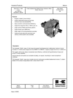
1 A4VG1/44RE 92 003 : Displacement Pump A4 VGfor closed circuitsSizes 3 Nominal pressure 400 barPeak pressure 450 Variable Displacement axial piston pump of swashplate designfor hydrostatic closed circuit transmissions flow is proportional to drive speed and Displacement and isinfinitely Variable output flow increases with swivel angle from 0 to its maximumvalue swivelling the pump over centre smoothly changes the directionof flow a highly adaptable range of control and regulating devices isavailable the pump is equipped with two pressure relief valves on thehigh pressure ports to protect the hydrostatic transmission(pump and motor) from overloads these valves also function as boost inlet valves an integral auxiliary pump serves as boost and pilot oil pump the maximum boost pressure is limited by a built-in boostpressure relief valve the integral pressure cut-off is standard Further Informations.
2 Variable Displacement Pump A4 VTGRE 92 012for drum drives on mobile concrete MixersRE 92 003 Code / Standard Pressure Relief Valve9 Pressure Cut-Off, D9HD - Hydraulic Control, Pilot Pressure Related10HW - Hydraulic Control, Mechanical Servo11DA - Hydraulic Control, Speed - Hydraulic Control, Direct Operated14EZ - Electrical Two-Position Control with Switching Solenoid14EP - Electrical Control, with Proportional Solenoid15 Unit Dimensions, Size Dimensions, Size Dimensions, Size Dimensions, Size Dimensions, Size Dimensions, Size Dimensions, Size Dimensions, Size Dimensions DA Control for Through Input and Through Drive Rotation Torques38 Combination Pumps39 Mechanical Stroke Limiter, M40 Ports X3 and X4 for Positioning Pressure, T40 Rotary Inch Valve41 Installation Situation for Coupling Assembly42 Preferred Types43 Brueninghaus Hydromatik2/44A4 VGRE 92 003 Code / Standard ProgramHydraulic fluidMineral oil (no code)Axial piston unitVariable swashplate design, nominal pressure 400 bar, peak pressure 450 barA4 VOperationPump in closed circuitsGSize Displacement Vg max in cm32840567190 125 180 250 Control device2840567190 125 180 250without control moduleNVNVH ydraulic control, pilot pressure relatedHDHDH ydraulic control, mechanical servoHWHWH ydraulic control, speed relatedDADAH ydraulic control, direct operatedDGDGE lectrical two-position control with switching solenoidEZEZE lectrical control with proportional solenoidEPEPS olenoid voltage (only for EP, EZ or DA)U = 12 V1U = 24 V2 Pressure cut-offwith pressure cut-off (standard)DZero position switch (only for HW)without zero position switch (no code)
3 With zero position switchLMechanical stroke limiterwithout mechanical stroke limiter (no code)with mechanical stroke limiter, external adjustableMPorts X3, X4 for positioning pressurewithout ports X3, X4 (no code)with ports X3, X4 TDA control valveNVEZDGEPHW HD DA DA control valve 1with DA control valve, fixed setting 2with DA control valve, mech. adjust. with control leverL 3LR 3 Rwith DA control valve, fixed setting and hydraulic inchvalve built-on, control with breaking fluid 4with DA control valve, mech. adjust. with control lever andL 5 Lhydraulic inch valve built-on, control with breaking fluidR 5 Rwith DA control valve, fixed settingand connections for master controller 7with DA control valve, fixed setting and hydraulic inchvalve built-on, control with mineral oil 8with DA control valve, mech. adjust. with control lever andL 9 Lhydraulic inch valve built-on, control with mineral oilR 9 RDA control valve with control leverwithout control lever (no code)with control lever - anti-clockwise operation directionLwith control lever - clockwise operation directionRSeries3 Index2 Direction of viewed on shaft endclockwiseRanti-clockwiseLA4VG3/44 Brueninghaus HydromatikA4V G/ 3 2 RE 92 003 piston unitOperationSizeControl deviceSeriesIndexDirection of rotation1) standard for - 1st pump: shaft Z2) standard for - 1st pump: shaft S3) with cold start valve = available = not available = preferred program (preferred types see page 43)Seals NBR, shaft seal in FPMNS haft end (permissible input torque see page 38)2840567190125 180 250 Splined shaft DIN 5480 (standard for single pump)ZSplined shaft DIN 5480 (standard for combi.
4 Pump, 1st pump) 1) 1) 1)ASplined shaft SAE (standard for single pump)SSplined shaft SAE (standard for combi. pump, 1st pump) 2) 2) 2)TSplined shaft SAE (only for combination pump, 2nd pump) UMounting flange2840567190 125 180 250 SAE2-hole C4-hole D2 + 4-hole FService line connections28 250 Ports A and B SAE, (metric fixing screws), at side (on opposite sides) 02 Ports A and B SAE, (metric fixing screws), at side (same side) 10 Auxiliary pump2840567190 125 180 250with integral auxiliary pump, without through driveF00without integral auxiliary pump, without through driveN00with integral auxiliary pump, with through integral auxiliary pump, with through driveflangehub2840567190 125 180 250 SAE A, 2-holeSAE A(N5/8"-9T 16/32DP)..01 SAE B, 2-holeSAE B(N7/8"-13T 16/32DP)..02 SAE B, 2-holeSAE B-B (N1"-15T 16/32DP)..04 SAE C, 2-holeSAE B-B (N1"-15T 16/32DP).
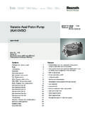
5 09 SAE C, 2-holeSAE C(N11/4"-14T 12/24DP) ..07 SAE D, 2+4-holeDIN 5480(N35x2x30x16x9H) ..73 SAE D, 2+4-holeSAE D(N13/4"-13T 8/16DP) ..69 SAE E, 4-holeSAE E(N13/4"-13T 8/16DP) ..72 Valvessetting range2840567190 125 180 250with high press. relief valve, pilot bar with bypass 1with high pressure relief valve, barwithout bypass 3direct controlled, (fixed setting)with bypass barwithout bypass 4with bypass 6 Filtration2840567190 125 180 250 Filtration in the suction line of the auxiliary (boost) pumpSFiltration in the pressure line of the auxiliary (boost) pump:ports for external boost circuit filter, (Fe and Fa)Dcold start valve and ports for external boost circuit filter, (Fe and Fa) Kfilter built-on (supplied complete) 3) Ffilter built-on with visual contamination indicator 3) Pfilter built-on with electrical contamination indicator 3) Lfilter built-on with visual and electrical contamination indicator 3) MExternal supply (model without integral auxiliary pump - N00, )EBrueninghaus Hydromatik4/44A4 VGtmin = -40 Ctmax = +115 C5104060201002004006001000160025000 20 40 60 80 100 -40 -20 -25 -10 10 30 50 90 115 70 0 VG 22VG 32VG 46VG 68VG 100 FluidWe request that before starting a poject detailed information aboutthe choice of pressure fluids and application conditions are takenfrom our catalogue sheets RE 90220 (mineral oil), RE 90221(environmentally acceptable hydraulic fluids) and RE 90223 (fireresistant hydraulic fluids, HF).
6 When using HF- or environmentally acceptable hydraulic fluidspossible limitations for the technical data have to be taken intoconsideration. If necessary please consult our technical department(please indicate type of the hydraulic fluid used for your applicationon the order sheet). The operation with HFA-, HFB and HFC- hydraulicfluids requires additional special viscosity rangeIn order to obtain optimum efficiency and service life, we recommendthat the operating viscosity (at operating temperature) be selectedfrom within the range: opt = operating viscosity mm2/sreferred to the circuit temperature (closed circuit).Viscosity limitsThe limiting values for viscosity are as follows: min =5 mm2/sshort term at a max. permissible temp. of tmax = 115 note that the max. fluid temperature is also not exceeded incertain areas (for instance bearing area). max = 1600 mm2/sshort term on cold start ( (n 1000 min-1, tmin = -40 C).)
7 At temperatures of -25 C up to -40 C special measures are contact us for further ( opt) (see shaded section of the selection diagram). Werecommend that the highest possible viscosity range should be chosenin each : At an ambient temperature of X C circuit temperature is 60 the operating viscosity range ( opt; shaded area) this correspondsto viscosity ranges VG 46 or VG 68. VG 68 should be : The leakage oil (case drain oil) temperature is influencedby pressure and pump speed and is always higher than the circuittemperature. However, at no point in the circuit may the temperatureexceed 115 it is not possible to comply with the above conditions because ofextreme operating parameters or high ambient temperatures pleaseconsult range of the radial shaft sealThe FPM shaft seal is admissible for a housing temperature rangefrom -25 C to +115 :For applications below -25 C a NBR shaft seal is necessary(admissible temperature range -40 C to +90 C).
8 When ordering, please state in clear text: with NBR shaft sealOperating pressure range - inletVariable pump (with external supply, E):for control devices EP, EZ, HW and HDboost pressure (when n = 2000 rpm) pSp_____20 barfor control devices DA, DGboost pressure (when n = 2000 rpm) pSp_____25 barAuxiliary pump:suction pressure ps min ( 30 mm2/s) _____ 0,8 bar absolutefor cold start _____ 0,5 bar absoluteOperating pressure range - outletVariable pump:Pressure at port A or Bnominal pressure pN_____400 barpeak pressure pmax_____450 barAuxiliary pump:peak pressure pH max_____40 bar(pressure data to DIN 24312)Case drain pressurePermissible case drain pressure at ports T1 and T2pL_____ 4 bar term (at start) _____ 6 bar positionOptional. The housing must be filled with fluid prior the com-missioning, and must remain full whenever it is extensive information on installation position, please consult ourdata sheet RE 90 270 before completing your design for installation position "drive shaft up" (only sizes 71-250):When ordering please state in clear text "installation position: driveshaft up".
9 The pump will be delivered with an additional air bleedport R1 located at the flange Datafluid temperature rangetemperature t in Cviscosity in mm2/sSelection diagramRE 92 003 on the selection of the hydraulic fluidIn order to select the correct fluid, it is necessary to know the operatingtemperature in the circuit (closed circuit) in relation to the hydraulic fluid should be selected so that within the operatingtemperature range, the operating viscosity lies within the optimumA4VG5/44 Brueninghaus HydromatikTechnical DataTable of values (theoretical values, without considering mh and v: values rounded)Size2840567190125180250 Displacementvariable pumpVg maxcm32840567190125180250auxiliary pump (at p = 20 bar)Vg Hcm36,18,611,619,619,628,339,852,5 Speedmax. speed with Vg maxnmax max. speed 1)nmax limitedrpm450042003900360033003250290026 00intermittent max. speed 2)nmax speednminrpm500500500500500500500500 Flowat nmax contin.
10 And Vg maxqv maxL/min 119160202234275356450600 Powerat nmax contin. p = 400 barPmaxkW79107134156183237300400 Torqueat Vg max p = 400 barTmaxNm17825535645157279511441590(vari able pump without aux. pump) p = 100 barTNm44,563,589112,8 143198,8 286398 Moment of inertia (about drive axis)Jkgm20,0017 0,0030,0051 0,0072 0,0106 0,0164 0,03230,0879 Weight (standard model without through drive) ) Limited maximum speed: at half corner power ( at Vg max and pN /2)2) Intermittent maximum speed: at high idling speed at engine overspeed: p = bar and Vg max with reversing heads: p < 300 bar and t < 5 of sizeVg n vOutput flowqv =in L/min 10001,59 Vg pVg pTorqueT = =in Nm 100 mh20 mhT n 2 T nqv pPowerP = = =in kW9549 60 000600 tVg= Displacement per revolution in cm3 p = differential pressure in barn= speed in rpm v= volumetric efficiency mh= mechanical-hydraulic efficiency t= overall efficiencyInput drivePermissible axial and radial loading on drive shaftSize2840567190125180250 Distance of Fq (from shaft collar)amm17,517,517,5202022,52529b mm3030303535404550cmm42,542,542,5505057, 56071max.