Transcription of Variable Displacement Pump A4VG - a-u-trade.ru
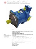
1 A4VG1/44RE 92 003 : Displacement Pump A4 VGfor closed circuitsSizes 3 Nominal pressure 400 barPeak pressure 450 Variable Displacement axial piston pump of swashplate designfor hydrostatic closed circuit transmissions flow is proportional to drive speed and Displacement and isinfinitely Variable output flow increases with swivel angle from 0 to its maximumvalue swivelling the pump over centre smoothly changes the directionof flow a highly adaptable range of control and regulating devices isavailable the pump is equipped with two
2 Pressure relief valves on thehigh pressure ports to protect the hydrostatic transmission(pump and motor) from overloads these valves also function as boost inlet valves an integral auxiliary pump serves as boost and pilot oil pump the maximum boost pressure is limited by a built-in boostpressure relief valve the integral pressure cut-off is standard Further Informations: Variable Displacement Pump A4 VTGRE 92 012for drum drives on mobile concrete MixersRE 92 003 Code / Standard Pressure Relief Valve9 Pressure Cut-Off, D9HD - Hydraulic Control, Pilot Pressure Related10HW - Hydraulic Control, Mechanical Servo11DA - Hydraulic Control, Speed - Hydraulic Control, Direct Operated14EZ - Electrical Two-Position Control with Switching Solenoid14EP - Electrical Control, with Proportional Solenoid15 Unit Dimensions, Size Dimensions, Size Dimensions, Size Dimensions, Size Dimensions.
3 Size Dimensions, Size Dimensions, Size Dimensions, Size Dimensions DA Control for Through Input and Through Drive Rotation Torques38 Combination Pumps39 Mechanical Stroke Limiter, M40 Ports X3 and X4 for Positioning Pressure, T40 Rotary Inch Valve41 Installation Situation for Coupling Assembly42 Preferred Types43 Brueninghaus Hydromatik2/44A4 VGRE 92 003 Code / Standard ProgramHydraulic fluidMineral oil (no code)Axial piston unitVariable swashplate design, nominal pressure 400 bar, peak pressure 450 barA4 VOperationPump in closed circuitsGSize Displacement Vg max in cm32840567190 125 180 250 Control device2840567190 125 180 250without control moduleNVNVH ydraulic control, pilot pressure relatedHDHDH ydraulic control, mechanical servoHWHWH ydraulic control, speed relatedDADAH ydraulic control.
4 Direct operatedDGDGE lectrical two-position control with switching solenoidEZEZE lectrical control with proportional solenoidEPEPS olenoid voltage (only for EP, EZ or DA)U = 12 V1U = 24 V2 Pressure cut-offwith pressure cut-off (standard)DZero position switch (only for HW)without zero position switch (no code)with zero position switchLMechanical stroke limiterwithout mechanical stroke limiter (no code)with mechanical stroke limiter, external adjustableMPorts X3, X4 for positioning pressurewithout ports X3, X4 (no code)with ports X3, X4 TDA control valveNVEZDGEPHW HD DA DA control valve 1with DA control valve, fixed setting 2with DA control valve, mech.
5 Adjust. with control leverL 3LR 3 Rwith DA control valve, fixed setting and hydraulic inchvalve built-on, control with breaking fluid 4with DA control valve, mech. adjust. with control lever andL 5 Lhydraulic inch valve built-on, control with breaking fluidR 5 Rwith DA control valve, fixed settingand connections for master controller 7with DA control valve, fixed setting and hydraulic inchvalve built-on, control with mineral oil 8with DA control valve, mech. adjust. with control lever andL 9 Lhydraulic inch valve built-on, control with mineral oilR 9 RDA control valve with control leverwithout control lever (no code)with control lever - anti-clockwise operation directionLwith control lever - clockwise operation directionRSeries3 Index2 Direction of viewed on shaft endclockwiseRanti-clockwiseLA4VG3/44 Brueninghaus HydromatikA4V G/ 3 2 RE 92 003 piston unitOperationSizeControl deviceSeriesIndexDirection of rotation1) standard for - 1st pump.
6 Shaft Z2) standard for - 1st pump: shaft S3) with cold start valve = available = not available = preferred program (preferred types see page 43)Seals NBR, shaft seal in FPMNS haft end (permissible input torque see page 38)2840567190125 180 250 Splined shaft DIN 5480 (standard for single pump)ZSplined shaft DIN 5480 (standard for combi. pump, 1st pump) 1) 1) 1)ASplined shaft SAE (standard for single pump)SSplined shaft SAE (standard for combi. pump, 1st pump) 2) 2) 2)TSplined shaft SAE (only for combination pump, 2nd pump) UMounting flange2840567190 125 180 250 SAE2-hole C4-hole D2 + 4-hole FService line connections28 250 Ports A and B SAE, (metric fixing screws), at side (on opposite sides) 02 Ports A and B SAE, (metric fixing screws), at side (same side)
7 10 Auxiliary pump2840567190 125 180 250with integral auxiliary pump, without through driveF00without integral auxiliary pump, without through driveN00with integral auxiliary pump, with through integral auxiliary pump, with through driveflangehub2840567190 125 180 250 SAE A, 2-holeSAE A(N5/8"-9T 16/32DP)..01 SAE B, 2-holeSAE B(N7/8"-13T 16/32DP)..02 SAE B, 2-holeSAE B-B (N1"-15T 16/32DP)..04 SAE C, 2-holeSAE B-B (N1"-15T 16/32DP) ..09 SAE C, 2-holeSAE C(N11/4"-14T 12/24DP) ..07 SAE D, 2+4-holeDIN 5480(N35x2x30x16x9H).
8 73 SAE D, 2+4-holeSAE D(N13/4"-13T 8/16DP) ..69 SAE E, 4-holeSAE E(N13/4"-13T 8/16DP) ..72 Valvessetting range2840567190 125 180 250with high press. relief valve, pilot bar with bypass 1with high pressure relief valve, barwithout bypass 3direct controlled, (fixed setting)with bypass barwithout bypass 4with bypass 6 Filtration2840567190 125 180 250 Filtration in the suction line of the auxiliary (boost) pumpSFiltration in the pressure line of the auxiliary (boost) pump:ports for external boost circuit filter, (Fe and Fa)Dcold start valve and ports for external boost circuit filter, (Fe and Fa) Kfilter built-on (supplied complete) 3) Ffilter built-on with visual contamination indicator 3) Pfilter built-on with electrical contamination indicator 3) Lfilter built-on with visual and electrical contamination indicator 3) MExternal supply (model without integral auxiliary pump - N00, )
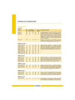
9 EBrueninghaus Hydromatik4/44A4 VGtmin = -40 Ctmax = +115 C5104060201002004006001000160025000 20 40 60 80 100 -40 -20 -25 -10 10 30 50 90 115 70 0 VG 22VG 32VG 46VG 68VG 100 FluidWe request that before starting a poject detailed information aboutthe choice of pressure fluids and application conditions are takenfrom our catalogue sheets RE 90220 (mineral oil), RE 90221(environmentally acceptable hydraulic fluids) and RE 90223 (fireresistant hydraulic fluids, HF).When using HF- or environmentally acceptable hydraulic fluidspossible limitations for the technical data have to be taken intoconsideration.
10 If necessary please consult our technical department(please indicate type of the hydraulic fluid used for your applicationon the order sheet). The operation with HFA-, HFB and HFC- hydraulicfluids requires additional special viscosity rangeIn order to obtain optimum efficiency and service life, we recommendthat the operating viscosity (at operating temperature) be selectedfrom within the range: opt = operating viscosity mm2/sreferred to the circuit temperature (closed circuit).Viscosity limitsThe limiting values for viscosity are as follows: min =5 mm2/sshort term at a max.