Transcription of VARIOUS CONTROL TECHNIQUES FOR POWER …
1 International Journal of POWER CONTROL Signal and Computation (IJPCSC) Vol. 4 No. 2 April- June -2012 gopalax journals,singapore ISSN:0976-268X Available at : 4 VARIOUS CONTROL TECHNIQUES FOR POWER QUALITY IMPROVEMENT USING DSTATCOM electronics and drives s engineering college Villupuram, DEVI electronics and drives s engineering college Villupuram, Abstract This paper focuses on the CONTROL TECHNIQUES employed for Distribution Static Compensator. Distributed static compensator is a device used for POWER quality improvement. Here we considered voltage source converter based distributed static compensator. It describes to CONTROL distribution Static Compensator employed at the distribution end. The phase shift CONTROL and AC bus /DC link voltage schemes have been incorporated to CONTROL DSTATCOM employed at the distribution end.
2 It describes the salient features of each strategy, with their merits and demerits. Keywords-DSTATCOM, harmonic mitigation, phase shift CONTROL , AC bus/DC link voltage regulation, POWER quality,reactive POWER compensationtor I. INTRODUCTION In a POWER distribution networks, reactive POWER is the main cause of increasing distribution system losses and VARIOUS POWER quality problems. Conventionally, static var compensators (SVC) have been used in conjunction with passive filters at the distribution level for reactive POWER compensation and mitigation of POWER quality problems [1].Though SVCs are very effective system controllers used to provide reactive POWER compensation at the transmission level, their limited bandwidth, higher passive element count that increases size and losses, and slower response make them inapt for the modern day distribution requirement.
3 Another compensating system has been proposed by[2],employing a combination of SVC and active POWER filter, which can compensate three phase loads in a minimum of two cycles. Thus, a controller which continuously monitors the load voltages and currents to determine the right amount of compensation required by the system and the less response time should be a viable alternative. Distribution static compensator(DSTATCOM) has the capacity to overcome the above mentioned drawbacks by providing precise CONTROL and fast response during transient and steady state. A DSTATCOM is basically a converter based distribution flexible AC transmission controller sharing many similar concepts with that of a static compensator(STATCOM) used at the transmission level.
4 At the transmission level, STACOM handles only fundamental reactive POWER and provides voltage support, while a DSTATCOM is employed at the distribution level or at the load end for dynamic compensation. The latter, DSTATCOM, can be one of the viable alternatives to SVC in a distribution network. Additionally, a DSTATCOM can also behave as a shunt active filter[3,4], to eliminate unbalance or distortion in the source current or the supply voltage, as per the IEEE-519 standard limits. Since a DSTATCOM is such a multifunctional device, the main objective of any CONTROL algorithm should me to make it flexible and easy to implement, in addition to exploiting its multi functionality to the maximum. Prior to the type of CONTROL algorithm incorporated, the choice of converter configuration is an important criterion. The two converter configurations are voltage source converter or current source converter, in addition to passive storage element either a capacitor or an inductor respectively.
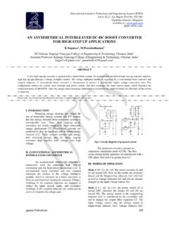
5 Normally, voltage source converter are preferred due to their smaller size, less heat dissipation and less cost of the capacitor, as compared to an inductor for the same rating[5-6]. This paper focuses on the comparative study of the CONTROL TECHNIQUES for voltage source converter based DSTATCOM, broadly classified into voltage CONTROL DSTATCOM and current CONTROL DSTATCOM. II. BASIC PRINCIPLE OF DSTATCOM A DSTATCOM is a controlled reactive source, which includes a voltage source converter (VSC) and a DC link capacitor connected in shunt, capable of generating and/ or absorbing reactive POWER . The operating principles of DSTATCOM are based on the exact equivalence of the conventional rotating synchronous compensator. The AC terminals of the VSC are not connected to the point of common coupling(PCC) through an inductance, which could be a filter inductance or leakage inductance of the coupling transformer , as shown in figure1.
6 International Journal of POWER CONTROL Signal and Computation (IJPCSC) Vol. 4 No. 2 April- June -2012 gopalax journals,singapore ISSN:0976-268X Available at : 5 Figure1: Basic Structure of Dstatcom The DC side of the converter is connected to a DC capacitor, which carries the input ripple current of the converter and is the main reactive storage element. This capacitor could be charged by a battery source, or could be precharged by the converter itself. If the output voltage of the VSC is equal to the AC terminal voltage, no reactive POWER is delivered to the system. If the output voltage is greater than the AC terminal voltage, the DSTATCOM is in the capacitive mode of operation and vice versa. The quantity of the reactive POWER flow is proportional to the difference in the two voltages. The voltage regulation at PCC and POWER factor correction cannot be achieved simultaneously.
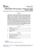
7 For a DSTATCOM used for voltage regulation at the PCC, the compensation should be such that the supply current should lead the supply voltages; whereas, for POWER factor correction, the supply current should be in phase with the supply voltages. The phase shift CONTROL are used to study the performance of a DSTATCOM for POWER factor correction and harmonic mitigation. III. CONTROL STRATEGIES The CONTROL strategies of a DSTATCOM are mainly implemented in the following steps: Measurement of system variables and signal conditioning. Extraction of reference compensating signals. Generation of firing angles for switching devices Figure2. shows the schematic diagram of DSTATCOM CONTROL . The generation of proper pulse width modulation (PWM) firing is the most important part of DSTATCOM CONTROL and it has a great impact on its compensation objectives, transients as well as steady state performance.
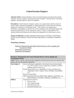
8 Since a DSTATCOM shares many concepts with that of STATCOM at the transmission level, a few CONTROL TECHNIQUES have been directly implemented to a DSTATCOM, incorporating PWM switching, rather than fundamental frequency switching(FFS) PWM based distribution static compensator offers faster response and capability for harmonic elimination. There are three methods of DSTATCOM for POWER factor correction and harmonic mitigation based on: 1. Phase shift CONTROL 2. Indirect decoupled current CONTROL 3. Regulation of AC bus and DC link voltage Figure2: Schematic diagram of DSTATCOM CONTROL IV. PHASE SHIFT CONTROL The schematic diagram of phase shift CONTROL is shown in figure3. In this method, the compensation is achieved by the measuring of the rms voltage at the load point, whereas no reactive POWER measurements are required [7,8].
9 Sinusoidal pulse width modulation technique is used with constant switching frequency. The error signal obtained by comparing the measured system rms voltage and the reference voltage is fed to the proportional integral(PI) controller, which generates the angle for deciding the necessary phase shift between the output voltage of the VSC and the AC terminal voltage. This angle is summed with the phase angle of the balanced supply voltages, assumed to be equally spaced at 120 degrees, to produce the desired synchronizing signal required to operate the PWM generator. In this scheme, the DC voltage is maintained constant, using a separate battery source. It is observed that the source current and the source voltage are in phase, correcting the POWER factor of the system in case of a linearly varying load; whereas, complete compensation is not achieved in case of nonlinear load (source current THD ) though this strategy is easy to implement, is robust and can provide partial reactive POWER compensation without harmonic suppression, it has the following disadvantages 1.
10 The controller does not use a self supporting DC bus and thus requires a very large DC source to pre charge the capacitor. 2. Balanced source supply as rms voltages assumed and the supply phase angle are calculated over the fundamental only. International Journal of POWER CONTROL Signal and Computation (IJPCSC) Vol. 4 No. 2 April- June -2012 gopalax journals,singapore ISSN:0976-268X Available at : 6 3. No harmonic suppression and partial compensation is achieved in case of nonlinear loads Figure3: Block Diagram of Phase Shift CONTROL V. REGULATION OF AC BUS AND DC LINK VOLTAGE Three phase AC supply voltages and DC link voltage are sensed and fed to two PI controllers, the outputs of which decide the amplitude of reactive and active current to be generated by the DSTATCOM[9]. Figure3 shows the block diagram of AC/DC link voltage scheme.