Transcription of Varistors Introduction - Vishay Intertechnology
1 Vishay BCCOMPONENTS. Resistive Products Technical Note Varistors Introduction GENERAL FEATURES. Varistors provide reliable and economical protection against Wide voltage range selection - from 14 VRMS to 680 VRMS. high voltage transients and surges which may be produced, This allows easy selection of the correct component for for example, by lightning, switching or electrical noise on AC the specific application. or DC power lines. They have the advantage over transient High energy absorption capability with respect to size of suppressor diodes in as much as they can absorb much component. higher transient energies and can suppress positive and Response time of less than 20 ns, clamping the transient negative transients. the instant it occurs. When a transient occurs, the varistor resistance changes Low stand-by power - virtually no current is used in the from a very high stand-by value to a very low conducting stand-by condition.
2 Value. The transient is thus absorbed and clamped to a safe Low capacitance values, making the Varistors suitable for level, protecting sensitive circuit components. the protection of digital switching circuitry. Varistors are manufactured from a non-homogeneous High body insulation - an ochre coating provides material, giving a rectifying action at the contact points of protection up to 2500 V, preventing short circuits to two particles. Many series and parallel connections adjacent components or tracks. determine the voltage rating and the current capability of the Available on tape with accurately defined dimensional varistor. tolerances, making the Varistors ideal for automatic insertion. Approved to UL 1449 edition 3 (file number: E332800) and manufactured using UL approved flame retardant materials.
3 Completely non flammable, in accordance with IEC, even under severe loading conditions. Non porous lacquer making the Varistors safe for use in humid or toxic environments. The lacquer is also resistant to cleaning solvents in accordance with IEC 60068-2-45. Varistors MANUFACTURING PROCESS. In order to guarantee top performance and maximum reliability, close in-line control is maintained over the automated manufacturing techniques. The manufacturing process flow chart shows each step of the manufacturing process, clearly indicating the emphasis on in-line control. Each major step in the manufacturing process shown in the Manufacturing process flow chart is described in the following sections: MILLING AND MIXING. TECHNICAL NOTE. Incoming materials are checked, weighed, milled and mixed for several hours to make a homogeneous mixture.
4 GRANULATION. A binder is added to produce larger granules for processing. PRESSING. The surface area and thickness of the disc help to determine the final electrical characteristics of the varistor, therefore pressing is a very important stage in the manufacturing process. The granulated powder is fed into dies and formed Manufacturing process flow chart into discs using a high speed rotary press. Revision: 04-Sep-13 1 Document Number: 29079. For technical questions, contact: THIS DOCUMENT IS SUBJECT TO CHANGE WITHOUT NOTICE. THE PRODUCTS DESCRIBED HEREIN AND THIS DOCUMENT. ARE SUBJECT TO SPECIFIC DISCLAIMERS, SET FORTH AT Technical Note Vishay BCcomponents Varistors Introduction FIRING QUALITY. The pressed products are first pre-fired to burn out the APPROVALS. binder. They are then fired for a controlled period and UL 1449 ed.
5 3 according file E332800. temperature until the required electrical characteristics are VDE following IEC 61051-1/2 according file 40002622 or obtained. Regular visual and electrical checks are made on 40013495. the fired batch. CSA file 219883 and cUL according file E332800. METALLIZATION The term QUALITY ASSESSMENT' is defined as the The fired ceramic discs are metallized on both sides with a continuous surveillance by the manufacturer of a product to silver content layer to produce good low resisitive electrical ensure that it conforms to the requirements to which it was contacts. Metallization is achieved by screen printing. visual made. checks are made regularly and a solderability test is carried PRODUCT AND PROCESS RELEASE. out in each production batch. Recognized reliability criteria are designed into each new ATTACHING LEADS product and process from the beginning.
6 Evaluation goes far beyond target specifications and heavy emphasis is Leads are automatically soldered to the metallized faces placed upon reliability. Before production release, new and regular strength tests are made. Three types of lead Varistors must successfully complete an extended series of configuration are available; one with straight leads, one with life tests under extreme conditions. straight leads and flange, and one with kinked leads. MONITORING INCOMING MATERIALS. LACQUERING Apart from carrying out physical and chemical checks on The components are coated by immersing them in a special incoming raw materials, a very close liaison with material non flammable ochre epoxy lacquer. Two coats are applied suppliers is maintained. Incoming inspection and product results are gradually fed back to them, so ensuring that they and the lacquer is cured.
7 Regular tests to check the coating also maintain the highest quality standards. thickness are made. IN-LINE CONTROL. ELECTRICAL TESTING (100 %). The manufacturing centre operates in accordance with the The voltage of each component is normally checked at requirements of IEC 61051-1 and UL 1449 . Each operator is two reference currents (1 mA and another according to the actively engaged in quality checking. In addition, in-line application). Any rejects are automatically separated for inspectors and manufacturing operators make regulated further evaluation. spot checks as a part of our Statistical Process Control (SPC). MARKING. FINAL INSPECTION AND TEST (100 %). All components are laser marked with type identification, voltage rating and date code. At the end of production, each varistor is inspected and tested prior to packing.
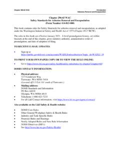
8 encapsulation intergranular boundary electrodes LOT TESTING. Before any lot is released, it undergoes a series of special lot tests under the supervision of the Quality department. PERIODIC SAMPLE TESTING. leads Component samples are periodically sent to the Quality laboratory for rigorous climatic and endurance tests to IEC/UL requirements. Data from these tests provide a valuable means of exposing long term trends that might otherwise pass unnoticed. The results of these tests are TECHNICAL NOTE. further used to improve the production process. V. (V) FIELD INFORMATION. 3 The most accurate method of assessing quality is monitoring performances of the devices in the field. Customer feedback is actively encouraged and the 100 I ( A). information is used to study how the components may be further improved.
9 This close relationship with customers is based on mutual trust built up over many years of co-operation. Revision: 04-Sep-13 2 Document Number: 29079. For technical questions, contact: THIS DOCUMENT IS SUBJECT TO CHANGE WITHOUT NOTICE. THE PRODUCTS DESCRIBED HEREIN AND THIS DOCUMENT. ARE SUBJECT TO SPECIFIC DISCLAIMERS, SET FORTH AT Technical Note Vishay BCcomponents Varistors Introduction DEFINITIONS In order to calculate the energy dissipated during a pulse, reference is generally made to a standardized wave of MAXIMUM CONTINUOUS VOLTAGE current. The wave prescribed by IEC 60 060-2 section 6 has The maximum voltage which may be applied continuously a shape which increases from zero to a peak value in a short between the terminals of the component. For all types of AC time, and thereafter decreases to zero either at an voltages, the voltage level determination is given by the approximate exponential rate, or in the manner of a heavily crest voltage x damped sinusoidal curve.
10 This curve is defined by the virtual lead time (t1) and the virtual time to half value (t2) as shown VOLTAGE AT 1 mA OR VARISTOR VOLTAGE. in the maximum energy curve (page 5). The voltage across a varistor when a current of 1 mA is The calculation of energy during application of such a pulse passed through the component. The measurement shall be is given by the formula: E = (Vpeak x I peak) x t2 x K. made in as short a time as possible to avoid heat perturbation. where: The varistor voltage is essentially a point on the V/I Ipeak = peak current characteristic permitting easy comparison between models Vpeak = voltage at peak current and types. = given for I = x Ipeak to Ipeak MAXIMUM CLAMPING VOLTAGE K is a constant depending on t2, when t1 is 8 s to 10 s The maximum voltage between two terminals when a (see table on page 8).