Transcription of VCU1525 Reconfigurable Acceleration Platform User Guide
1 VCU1525 . Reconfigurable Acceleration Platform User Guide UG1268 ( ) March 22, 2019. Revision History The following table shows the revision history for this document. Date Version Revision 03/22/2019 Removed references to PCIe Gen4. Updated graphics to remove schematic detail. Updated QSFP28 Module Connectors. Updated and moved Appendix A Board Installation into Chapter 3, Board and Deployment Software Installation. Updated Markings in Appendix A, Regulatory and Compliance Information. 09/27/2018 Added the Electrostatic Discharge Caution section. Renamed heading QSFP28 Module Connectors and updated the section (28 Gb/s QSFP+ became QSFP28 throughout). Updated banks in Figure 3-1. Renamed Figure 3-1. Updated DDR4 DIMM Memory. Note: Figure numbers are accurate as of version 08/07/2018 Revised Step 4: Program the Base Platform .
2 Note: This citation was accurate as of version 07/09/2018 Revised Board Features, Board Specifications, Table 2-1, VCU1525 Board Installation, and Figure 3-1. Removed xilinx constraints file information. Added , Board and Deployment Software Installation. Note: Table and figure numbers are accurate as of version 04/02/2018 Revised Board Specifications and VCU1525 Board Installation. Updated Table 2-1, Table 2-2, and Table 3-2. Revised paragraph after Table 3-1. Added Figure 3-2. Updated Figure 3-3, Figure 3-4, and Figure 3-1. Revised Appendix A, Regulatory and Compliance Information. Note: Table and figure numbers are accurate as of version 11/13/2017 Initial xilinx release. VCU1525 Acceleration Platform User Guide Send Feedback 2. UG1268 ( ) March 22, 2019 Table of Contents Revision History .. 2. Chapter 1: Introduction Overview.
3 5. Block Diagram .. 7. Board Features .. 8. Board Specifications .. 9. Dimensions .. 9. Environmental .. 9. Operating Voltage .. 9. FPGA Configuration .. 10. Chapter 2: Board Component Descriptions Overview .. 11. Feature Descriptions .. 11. Virtex UltraScale+ XCVU9P-L2 FSGD2104E FPGA ..11. DDR4 DIMM Memory ..11. Quad SPI Flash Memory ..12. USB JTAG Interface ..12. FT4232HQ USB-UART Interface ..12. PCI Express Endpoint ..13. QSFP28 Module Connectors ..13. I2C Bus ..14. Status LEDs ..14. VCU1525 Board Power System ..15. Chapter 3: Board and Deployment Software Installation Introduction .. 16. Safety and Antistatic Precautions.. 16. Electrostatic Discharge Caution ..16. Step 1: Board Installation .. 17. Step 2: Deployment Software Installation .. 18. XRT and Deployment Shell Installation Procedures on RedHat and CentOS.
4 18. XRT and Deployment Shell Installation Procedures on Ubuntu ..21. Step 3: Board Bring-Up and Validation.. 23. Running lspci ..23. Running xbutil flash scan ..24. Running xbutil validate ..24. VCU1525 Acceleration Platform User Guide Send Feedback 3. UG1268 ( ) March 22, 2019 Step 4: Installing the Development Software .. 25. Generating the xbutil flash Command .. 25. Troubleshooting.. 27. Appendix A: Regulatory and Compliance Information Overview .. 29. CE Directives.. 29. CE Standards.. 29. Electromagnetic Compatibility ..29. Safety ..30. Markings .. 30. Appendix B: Additional Resources and Legal Notices xilinx Resources .. 31. Documentation Navigator and Design Hubs .. 31. References .. 32. Please Read: Important Legal Notices .. 33. VCU1525 Acceleration Platform User Guide Send Feedback 4. UG1268 ( ) March 22, 2019 Chapter 1.
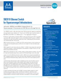
5 Introduction Overview The VCU1525 Reconfigurable Acceleration Platform is a peripheral component interconnect express (PCIe ) Gen3 x16 compliant board featuring the xilinx Virtex UltraScale+ . XCVU9P-L2 FSGD2104E FPGA. This xilinx FPGA-based PCIe accelerator board is designed to accelerate compute-intensive applications like machine learning, data analytics, and video processing. The VCU1525 board is available in both active and passive cooling configurations and designed to be used in cloud data center servers. Figure 1-1 shows the VCU1525 active cooling configuration (PC applications). X-Ref Target - Figure 1-1. X20017-110217. Figure 1-1: VCU1525 Reconfigurable Acceleration Platform (Active Cooling). VCU1525 Acceleration Platform User Guide Send Feedback 5. UG1268 ( ) March 22, 2019 Chapter 1: Introduction Figure 1-2 shows the VCU1525 passive cooling configuration (data center server applications).
6 X-Ref Target - Figure 1-2. X20018-110217. Figure 1-2: VCU1525 Reconfigurable Acceleration Platform (Passive Cooling). CAUTION! The VCU1525 board with passive cooling is designed to be installed into a data center server, where controlled air flow provides direct cooling. The VCU1525 board with active cooling is designed to be installed into a PC environment where the air flow is uncontrolled, hence this configuration has the heat sink and fan enclosure cover installed to provide appropriate cooling. In either cooling configuration, the board enclosure makes the board top-side components inaccessible (except the triple-LED module DS3 which protrudes through the left front end PCIe bracket). Board details revealed in this user Guide are provided to aid understanding of board features. If the cooling enclosure is removed from either configuration of the board and it is powered-up, external fan cooling airflow MUST be applied to prevent over-temperature shut-down and possible damage to the board electronics.
7 See Appendix B, Additional Resources and Legal Notices for references to documents, files, and resources relevant to the VCU1525 board. VCU1525 Acceleration Platform User Guide Send Feedback 6. UG1268 ( ) March 22, 2019 Chapter 1: Introduction Block Diagram A block diagram of the VCU1525 board is shown in Figure 1-3. X-Ref Target - Figure 1-3. 244-pin DIMM interface 64-bit + ECC dual rank support x4/x8 UDIMM support PC4-2400 compatible C0. Clocks 244-pin DIMM interface 64-bit + ECC dual rank support x4/x8 UDIMM support PC4-2400 compatible XADC C2. 244-pin DIMM interface 64-bit + ECC dual rank support LEDs x4/x8 UDIMM support PC4-2400 compatible C3. VU9P. D2104. QSFP #2 244-pin DIMM interface 64-bit + ECC dual rank support x4/x8 UDIMM support PC4-2400 compatible QSFP #1 C1. QSPI. DIP SW POWER. PCIe GEN1/2/3 x 1/2/4/8/16.
8 X19964-022419. Figure 1-3: VCU1525 Board Block Diagram VCU1525 Acceleration Platform User Guide Send Feedback 7. UG1268 ( ) March 22, 2019 Chapter 1: Introduction Board Features The VCU1525 board features are listed in this section. Detailed information for each feature is provided in Feature Descriptions in Chapter 2. Virtex UltraScale+ XCVU9P-L2 FSGD2104E FPGA. Memory (four independent dual-rank DDR4 interfaces). 64 gigabyte (GB) DDR4 memory 4x DDR4 16 GB, 2400 mega-transfers per second (MT/s), 64-bit with error correcting code (ECC) DIMM. x4/x8 unregistered dual inline memory module (RDIMM) support Configuration options 1 gigabit (Gb) Quad Serial Peripheral Interface (SPI) flash memory Micro-AB universal serial bus (USB) JTAG configuration port 16-lane PCI Express Two QSFP28 100G interfaces USB-to-UART FT4232HQ bridge with Micro-AB USB connector Integrated Endpoint block for PCI Express connectivity Gen1, 2 or 3 x1/x2/x4/x8/x16.
9 I2C bus Status LEDs Power management with system management bus (SMBus) voltage, current, and temperature monitoring Dynamic power sourcing based on external power supplied 75W PCIe slot functional with 35 A max VCCINT current PCIe slot power only 150 W PCIe slot functional with 110 A max VCCINT current PCIe slot power and 6-pin PCIe Aux power cable connected 225 W PCIe slot functional with 160 A max VCCINT current PCIe slot power and 8-pin PCIe Aux power cable connected Two QSFP28 100G interfaces Onboard reprogrammable flash configuration memory Front panel JTAG and universal asynchronous receiver-transmitter (UART) access through the USB port VCU1525 Acceleration Platform User Guide Send Feedback 8. UG1268 ( ) March 22, 2019 Chapter 1: Introduction FPGA configurable over USB/JTAG and Quad SPI configuration flash memory Thermal management with variable rate fan for minimal fan noise (active version).
10 Board Specifications Dimensions Height: inch ( cm). PCB thickness ( 5%): inch ( cm). Board length, passive heat sink: inch ( cm). Board length, active heat sink: inch (29 cm). Board thickness with heat sink enclosure installed: Active: inch ( cm). Passive: inch ( cm). Dual slot PCIe full-length, full height form-factor compliant Note: A 3D model of this board is not available. Environmental Temperature Operating: 0 C to +45 C. Storage: 25 C to +60 C. Humidity 10% to 90% non-condensing Operating Voltage PCIe slot +12 V DC, + V DC, + VAUXDC, External +12 VDC. VCU1525 Acceleration Platform User Guide Send Feedback 9. UG1268 ( ) March 22, 2019 Chapter 1: Introduction FPGA Configuration The VCU1525 board supports two UltraScale+ FPGA configuration modes: Quad SPI flash memory JTAG using USB JTAG configuration port lower connector in the PCIe bracket The FPGA bank 0 mode pins are hardwired to M[2:0] = 001 Master SPI mode with pull-up/down resistors.