Transcription of VD - Marathon Electric
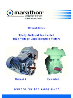
1 VD SeriesVariable Speed MotorsTotally enclosed Fan CooledLow Voltage Ac Cage Induction MotorsVDMotors for the Long Run!A REGAL-BELOIT COMPANYMARATHON Electric introduces VD series motorstailor made for inverter drives having enhanceddielectric strength and adequate thermal margin suitablefor variable speed technology involving high switching frequencyIGBT drive has enabled AC induction motors to beoperated as variable speed drives. However, therehad been a documented increase of premature windingfailure for standard general purpose motors whenoperated with inverter and steep front voltage spikes (dV/dT) producedby latest generation IGBT drives associated with thephenomenon of voltage wave reflection due to longercable length imposes stress on the motor windingresulting rapid ageing and deterioration of rating for Variable speed motors need to beselected based on following aspects-lHeating due to harmonic content of ventilation due to low speed torque/Constant Power/ Variable torquerequirement of limiting factors eg.
2 Maximum permissiblemotor speed, ambient temp. altitude variable speed drives provide highest energysaving for variable torque (Centrifugal pump, fan)applications, for constant torque and constant powerapplication, Variable speed drives offer significantprocess control improvements. Basic inverters permitoperation over a typical 20:1 speed range. Withclosed loop vector control the effective range may beincreased to 1000 of OperationSo far DC motor had been the only choice whereprecise torque and speed control was required. ACinduction motor has no direct control over the currentsof the rotor, so a rapid transient response from onesteady state to another had been a problem. Throughhighly sophisticated motor modeling algorithms andinternal circuitry, the vector control drive has solvedthis problem. With quick instantaneous changes in thestator current, quick instantaneous changes occur inthe rotor current.
3 Vector drive manipulates the motortorque by indirectly controlling the current of the rotorthrough the stator windings. Calculating and quantifyingthe corresponding changes in the rotor current is theStandardsVD series motors are manufactured to thefollowing national and International IEC/TS-60034-17/MG1-Pt30 & 31 IEC/TS-60034- 25 CoolingIS6362 IEC 60034-6 Table 31genius of the vector vector control drives also require positionfeedback from a shaft mounted encoder. Vector Controlassociated with space vector modulation techniquesfor voltage source inverters have enabled to achievehigh quality current and torque response using inductionmotor voltage source inverters employing PWM controlis employed for variable speed drives. PWM voltagesource inverters employ a converter section comprisingof a rectifier bridge supplying power to DC link filterwhich operates at a nominal constant voltage.
4 The DClink supply is fed to the inverter section converting DCto AC through a 3 Phase bridge comprising highspeed switching devices (IGBT) producing a variablevoltage variable frequency sinusoidal supply for would deliver a proportional voltage andfrequency up to base voltage (V1) and base frequencyf1 (Corresponding base speed n1) set by the base frequency, voltage (V1) remains fixedas per available supply voltage up to maximumpermissible frequency f2 (Corresponding speed n2)and f3 (Corresponding speed n3). Motor output ratingbecomes proportional to frequency up to f1 and motoroutput remains constant beyond f1 up to f2 and motoroperates with reduced output upto maximumpermissible frequency f3. f2 is normally decided bylimiting motor temp. rise owing to higher iron lossat higher frequency and high windage loss (Selfcooled motors) and minimum requirement.
5 F3is decided mainly based on max. speed limitationimposed by bearing and rotor assembly. Operatingflux of the motor remains constant up to base frequency(f1) by keeping V/f as constant. However, at lowfrequencies (<10Hz.) it is necessary to provide voltageboost to maintain required 1 Typical sine wave generated by inverter pulseSpeed (n)Torque (T)Power (P)Voltage (V)o n1 Constantp nV/f1n1 n2T ConstantV1n11n2 n3T P V1n2nTable 1 Note :n1=Speed at base frequency (f1)n2=Maximum speed at max. motor torquen3=Maximum Speed at reduced outputPoweron1n2n3 SpeedFig. 3 PnVoltageFrequencyf1f2f3V1 Fig. 4VD series motors meet in general for Definite Purpose Inverter Fed Motors .VD series motors up to 460V base voltage aredesigned for lPeak voltage -1600V MaxlCarrier Switching Frequency : 3-5 KhzslVoltage rise time> harmonic distortion< with still higher base voltage up to 690V aredesigned suitable for still higher peak Voltage and frequencyStandard motors are suitable for operation for a mainssupply of 3 Phase, 415V+/-10%, 50Hz.
6 +/-5% .However, motors can be offered for any base voltagefrom 200 Volt to series motors are provided with IP55 degree ofprotection as standard. IP56 degree of protection canbe provided on VD series motors are designed for S1 series crane duty motors suitable for S4/S5 dutyratings are available as a seperate range. Motor tosuit other duty conditions may be offered on and Temp. riseThe motors are designed suitable for 45 C ambienttemperature and provided with class F insulation withtemp. rise limiting to class B limit. Research have shownthat thermal margin enhances dielectric performanceof inverter fed motors significantly. Class H insulationmay be offered on request. Motor re-rating factor dueto ambient temperature and altitude is indicated inthe motor selection chart. Apart from many otherspecific design considerations, VD series motors areprovided with special insulation system to withstandvoltage stresses imposed by IGBT based drivescomprising of the grade of wire insulation depending onmotor ratinglVacuum impregnation /Multi dip treatmentlTropicalisation treatmentlPhase separator/Overhang tapeCoolingStandard motors are suitable for operation with shaftmounted fan with standard IC411 cooling forms of cooling is given SizeOutput RangeAluminumVDA63 VDA 180L4 Pole : Pole : VD 355L4 Pole : 280KW6 Pole : IronVK355S VK400L4 Pole:180KW-315 KWBody6 Pole :160KW-280 KWVDC315F-VDC355F4 Pole : 350KW-560 KWTable 2 Fig.
7 2 Typical Voltage Source PWM inverterMAINSINDC LINKCAPACITORDC LINK CHOKESUPPLY CONVERTORMACHINE CONVERTOROUTPUT2 FrameSupplyCurrent Input Increase in Overall LengthAir DeliveryAmpsWattsWithout Encoder ,415V, 6 CodeArrangementIC411 totally enclosed Fan cooled . Motorcooled by its own shaft driven externallymounted fan. Cooling effect reduces withreduction of speed. Overspeedingincreases Windage loss and noise levelIC410 totally enclosed Non ventilated (TENV).Free convection (self cooling), no externalmounted fan,IC418 totally enclosed Air Over Motor cooledby airstream. Cooling effect reduces withreduced airstream 416 totally enclosed Force cooled . Motorcooled by independent throughout speed 4 Consideration for Variable speed operationVariable speed drives are used for operation both atlow and high speed.
8 Cooling for variable speedmotors gets affected while operating at lower speedwhereas during high speed operation windage losses,bearing lubrication, increase in noise level, increasedtemp. due to shaft seals if any require special permissible speed for standard VD series motoris indicated in Table 5. At low speed (Below 10Hz.)loss distribution changes substantially which may leadto higher surface temp. Temp. rise near bearinglocation should be periodically checked to ascertainthat they are within limit. For sustained operation atlow speed separate Force ventilation (FV) unit isrecommended. FV unit is also used to restrict windageloss and motor noise when the motor runs frequentlynear to highest permissible operating speed of thebearing system. For applications necessitating higherspeed than 80Hz.
9 Refer to Size Maximum permissible - 2 Pole3600315-4,6 Pole3000355-2 pole3600355-4, 6 Pole2500 Table 5 Force Ventilation UnitForce ventilation unit replaces integral shaft mountedfan with an independently mounted separately excitedmotor driven fan. The unit provides constant airflowto the drive motor throughout speed range. TotallyEnclosed Air over motor /TEFC motor, depending onthe design of FV unit, is provided to drive theindependent fan. Fan motor rating depends on therating and size of drive motor. Specially designedaxial flow fan with optimized air delivery, low noiselevel and minimum power input is table provides brief specification of standardFV unit. However, FV unit specification is normallyreviewed with drive requirement and is subject tochange as size Ball and Roller bearings are used.
10 Doublesealed bearings are provided with high temp. greasesuitable for operation upto 110 C. Grease reliefarrangement is provided for motors having re-greasing Drive SizeEnd BearingEnd Bearing806204ZZ6204ZZ906205ZZ6204ZZ10062 06ZZ6205ZZ1126206ZZ6205ZZ1326208ZZ6207ZZ 1606309ZZ6209ZZ1806310ZZ6210ZZ2006312631 0ZZ225631363132506314631328063176314315 S/M-2 pole63176316315S/M- >4 Pole63196316315M/L- 2 Pole63176317315M/L- >4 Pole63196319(For bigger sizes refer to Marathon Electric )Table 7 Bearing CurrentDepending on motor size and supply voltage rating,bearing current may be generated owing to shaftvoltage caused by high dV/dT common mode voltage(CMV) and motor parasitic capacitance. Normallybearing fluting caused by such bearing currents arenoted from motor rating 110KW upwards. For framesizes 280 and above insulated bearing housing isprovided as standards.