Transcription of VDR Metal Oxide Varistors High Surge - Vishay
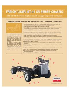
1 VDRH BCcomponents Revision: 19-Jun-151 Document Number: 29082 For technical questions, contact: DOCUMENT IS SUBJECT TO CHANGE WITHOUT NOTICE. THE PRODUCTS DESCRIBED HEREIN AND THIS DOCUMENTARE SUBJECT TO SPECIFIC DISCLAIMERS, SET FORTH AT Metal Oxide Varistors high SurgeORDERING INFORMATIONThe Varistors are available in a number of packaging options: Bulk On tape on reel On tape in ammopackThe basic ordering code for each option is given in tables titled Varistors on Tape on Reel, Varistors on Tape in Ammopack, and Varistors in Bulk. To complete the catalog number and to determine the required operating parameters, see Electrical Data and Ordering Information Special lead-configuration as inside or outside crimped leads on Low high purity zinc Oxide disc Halogen free insulating epoxy coating Straight or kinked leads Higher current Surge /size ratio capability up to 10 kA for H20 types Certified according to UL 1449 edition 3, VDE/IEC 61051-1/2 and CSA Material categorization: for definitions of compliance please see APPLICATION Overvoltage and transient voltage protectionDESCRIPTIONThe Varistors consist of a disc of low- ceramic material with two solid copper leads (H20 types only) or copper clad steel wire.
2 The wires have a matte tin plating. They are coated with a layer of ocher colored halogen- free epoxy, which provides electrical, mechanical and climatic protection. The encapsulation is resistant to all cleaning solvents in accordance with IEC Varistors are suitable for processing on automatic insertion, cutting and bending Soldering235 C, duration: 5 s (Pb-bearing) 245 C, duration: 5 s (lead (Pb)-free)Resistance to Soldering Heat260 C; duration: 10 s Varistors are marked with the following information: Maximum continuous RMS voltage with - E suffix series number (582, 583, 584, 585 or 586) Manufacture logo Date of manufacture (YYWW) Safety marks on VDRH10-14-20 typesINFLAMMABILITYThe Varistors are passive non-flammable. The encapsulation is made of flame resistant epoxy in accordance with UL 94 REFERENCE DATAPARAMETERVALUEUNITM aximum continuous voltage in operating temperature range:RMS11 to 680 VDC14 to 895 VMaximum non-repetitive transient current INRP (8 x 20 s)250 to 10 000 AMaximum energy (10/1000 s) to 620 JDetailed specificationBased onIEC 61051-1 IEC 61051-2 IEC 61051-2-2 Storage temperature-40 to +150 COperating temperature-40 to +125 CVDRH BCcomponents Revision: 19-Jun-152 Document Number: 29082 For technical questions, contact: DOCUMENT IS SUBJECT TO CHANGE WITHOUT NOTICE.
3 THE PRODUCTS DESCRIBED HEREIN AND THIS DOCUMENTARE SUBJECT TO SPECIFIC DISCLAIMERS, SET FORTH AT DATA AND ORDERING INFORMATIONMAXIMUM CONTINUOUS VOLTAGEVOLTAGE (3)at 1 mAMAXIMUMVOLTAGEat STATEDCURRENTMAXIMUMENERGY (4)(10 x 1000 s) (5)INRP (8 x 20 s)TYPICALCAPACITANCEat 1 kHzT(max.)EUL 1449ED3 SPDTYPE (7)CATALOGNUMBERS (1)RMS (2) (V)DC(V)(V)V(V)I(A)(J)(A)(pF)(mm)(mm)SAP (6) BCcomponents Revision: 19-Jun-153 Document Number: 29082 For technical questions, contact: DOCUMENT IS SUBJECT TO CHANGE WITHOUT NOTICE. THE PRODUCTS DESCRIBED HEREIN AND THIS DOCUMENTARE SUBJECT TO SPECIFIC DISCLAIMERS, SET FORTH AT DATA AND ORDERING INFORMATIONMAXIMUM CONTINUOUS VOLTAGEVOLTAGE (3)at 1 mAMAXIMUMVOLTAGEat STATEDCURRENTMAXIMUMENERGY (4)(10 x 1000 s) (5)INRP (8 x 20 s)TYPICALCAPACITANCEat 1 kHzT(max.)
4 EUL 1449ED3 SPDTYPE (7)CATALOGNUMBERS (1)RMS (2) (V)DC(V)(V)V(V)I(A)(J)(A)(pF)(mm)(mm)SAP (6)VDRH BCcomponents Revision: 19-Jun-154 Document Number: 29082 For technical questions, contact: DOCUMENT IS SUBJECT TO CHANGE WITHOUT NOTICE. THE PRODUCTS DESCRIBED HEREIN AND THIS DOCUMENTARE SUBJECT TO SPECIFIC DISCLAIMERS, SET FORTH AT DATA AND ORDERING INFORMATIONMAXIMUM CONTINUOUS VOLTAGEVOLTAGE (3)at 1 mAMAXIMUMVOLTAGEat STATEDCURRENTMAXIMUMENERGY (4)(10 x 1000 s) (5)INRP (8 x 20 s)TYPICALCAPACITANCEat 1 kHzT(max.)EUL 1449ED3 SPDTYPE (7)CATALOGNUMBERS (1)RMS (2) (V)DC(V)(V)V(V)I(A)(J)(A)(pF)(mm)(mm)SAP (6)VDRH BCcomponents Revision: 19-Jun-155 Document Number: 29082 For technical questions, contact: DOCUMENT IS SUBJECT TO CHANGE WITHOUT NOTICE.
5 THE PRODUCTS DESCRIBED HEREIN AND THIS DOCUMENTARE SUBJECT TO SPECIFIC DISCLAIMERS, SET FORTH AT (1)The products are certified according to (c)UL (E332800), VDE (40013495), and CSA (219883)(2)The sinusoidal voltage is assumed as the normal operating condition. If a non-sinusoidal voltage is present, type selection should be based on multiplying the peak voltage by a factor of (3)The voltage measured at 1 mA meets the requirements of IEC 61051. The tolerance on the voltage at 1 mA is 10 %. (4) high energy surges are generally of longer duration. The maximum energy for one pulse of 10 x 1000 s is given as a reference for longer duration pulses. This pulse can be characterised by peak current (Ip) and pulse width t2 (virtual time of half Ip value, following IEC 60060-2, section 6 ). If Vp is the clamping voltage corresponding to Ip, the energy absorbed in the varistor is determined by the formula: where K is dependent on the value of t2 (see Peak Current as a Function of Pulse Width drawing).
6 (5)A current wave of 8 x 20 s is used as a standard for pulse current and clamping voltage ratings. The maximum non-repetitive transient current is given for one pulse applied during the life of the component.(6)For composition of the SAP part number: Replace x byB for bulk typeReplace y by Sfor straight leads T for tape and reelKfor kinked leads (bulk only) A for tape and ammopackLfor kinked leads with H0 = 16 mm (tape and reel/ammo) Mfor kinked leads with H0 = mm (tape and reel/ammo)(7)All Varistors are recognized under VZAC2/VZCA8 Surge protective devices, components type 4 as specified in UL 1449 edition 3 for operating temperatures up to 85 C. The parts with indication type 2 or 3 SPD s, are tested and certified to be used in type 2 or 3 SPD applications for operating temperatures up to 85 C. The parts with indication type 5 SPD, are tested and certified for operation up to 105 C ambient temperature for use in type 2 SPD applications with nominal discharge current of 3 kA.
7 The final acceptance of the component is dependent upon its installation and use in complete equipment submitted to underwriters laboratories Inc. DATA AND ORDERING INFORMATIONMAXIMUM CONTINUOUS VOLTAGEVOLTAGE (3)at 1 mAMAXIMUMVOLTAGEat STATEDCURRENTMAXIMUMENERGY (4)(10 x 1000 s) (5)INRP (8 x 20 s)TYPICALCAPACITANCEat 1 kHzT(max.)EUL 1449ED3 SPDTYPE (7)CATALOGNUMBERS (1)RMS (2) (V)DC(V)(V)V(V)I(A)(J)(A)(pF)(mm)(mm)SAP (6)EK x Vp x Ip x t2=VDRH BCcomponents Revision: 19-Jun-156 Document Number: 29082 For technical questions, contact: DOCUMENT IS SUBJECT TO CHANGE WITHOUT NOTICE. THE PRODUCTS DESCRIBED HEREIN AND THIS DOCUMENTARE SUBJECT TO SPECIFIC DISCLAIMERS, SET FORTH AT CHARACTERISTICSDERATING CURVEPEAK CURRENT AS A FUNCTION OF PULSE WIDTHNote(1)Tmax.
8 And E values per size and voltage level can be found back in the Electrical Data tableELECTRICAL DATAPARAMETERVALUEUNITM aximum continuous voltage:RMS11 to 680 VDC14 to 895 VMaximum non-repetitive transient current (INRP) (8 x 20 s) VDRH05250 or 800A VDRH07500 or 1750A VDRH10 1000 or 3500A VDRH142000 or 6000A VDRH203000 or 10 000 AThermal resistance: VDRH05 80 K/W VDRH07 70K/W VDRH10 60K/W VDRH14 50K/W VDRH20 40K/WMaximum dissipation: VDRH05100mW VDRH07250mW VDRH10400mW VDRH14600mW VDRH201000mWTemperature coefficient of voltage at 1 mA maximum proof between interconnected leads and case2 500 VStorage temperature-40 to +150 COperating temperature-40 to +125 C100 %0- 40125 Tamb ( C)Maximum VoltageMaximum DissipationMaximum EnergyMaximum Transient Current150t ( s)t2t1Ip(%)1000105090t2 ( s) DIMENSIONS (BULK TYPE) in millimeters AND CATALOG NUMBERSD (1) (1)dFCATALOGNUMBERV 320 V V > 320 V V 300 V V > 300 V V 320 V V > 320 to to to to to BCcomponents Revision: 19-Jun-157 Document Number: 29082 For technical questions, contact: DOCUMENT IS SUBJECT TO CHANGE WITHOUT NOTICE.
9 THE PRODUCTS DESCRIBED HEREIN AND THIS DOCUMENTARE SUBJECT TO SPECIFIC DISCLAIMERS, SET FORTH AT in millimeters: See Component Dimensions and Electrical Data tableVARISTORS IN 5 mm11 V to 460 7 mm11 V to 510 10 mm11 V to 680 14 mm11 V to 680 20 mm11 V to 680 VStraight leads; see outline of components with straight leads drawingBSEBSEBSEBSEBSEK inked leads; see outline of components with kinked leads drawingBKEBKEBKEBKEBKEP ackaging quantities11 V to 95 V25025025010050130 V to 385 V25025025010050420 V to 460 V25025020010050485 V to max. V-25015010050dDATLEFdA0 LDTFOUTLINE of Component with Straight LeadsOUTLINE of Component with Kinked LeadsVDRH BCcomponents Revision: 19-Jun-158 Document Number: 29082 For technical questions, contact: DOCUMENT IS SUBJECT TO CHANGE WITHOUT NOTICE. THE PRODUCTS DESCRIBED HEREIN AND THIS DOCUMENTARE SUBJECT TO SPECIFIC DISCLAIMERS, SET FORTH AT (1)Except for 35 V and 40 V = 1000 pieces DIMENSIONS OF AMMOPACK in millimetersVARISTORS ON TAPE IN 5 mm11 V to 460 7 mm11 V to 510 10 mm11 V to 680 14 mm11 V to 680 VStraight leadsH = 18 mm--ASEASEH = 20 mmASEASE--See drawing: taped version with straight leadsKinked leadsH0 = mmAMEAMEAMEAMEH0 = 16 mmALEALEALEALESee drawing: taped version with kinked leadsPackaging quantities14 V to 210 V1500 (1)1500 (1)500500230 V to 510 V10001000500500550 V to max.
10 V--400400340 or 55 BCcomponents Revision: 19-Jun-159 Document Number: 29082 For technical questions, contact: DOCUMENT IS SUBJECT TO CHANGE WITHOUT NOTICE. THE PRODUCTS DESCRIBED HEREIN AND THIS DOCUMENTARE SUBJECT TO SPECIFIC DISCLAIMERS, SET FORTH AT ON TAPE AND 5 mm11 V to 460 7 mm11 V to 510 V 10 mm11 V to 680 14 mm11 V to 680 VStraight leadsH = 18 mm--TSETSEH = 20 mmTSETSE--See drawing: taped version with straight leadsKinked leadsH0 = mmTMETMETMETMEH0 = 16 mmTLETLETLETLESee drawing: taped version with kinked leadsPackaging quantities14 V to 250 V150015001000750275 V to 300 V15001500750750320 V to 350 V10001000500500385 V to max. V10001000500500T h hAT1tLP0P1D0 FdDP p pW0W2W1 HWTAPED VERSION WITH STRAIGHT LEADS (only for VDRH05 and VDRH07)T h hAT1tP0P1D0 FdDP p pW0W2W1 HWTAPED VERSION WITH STRAIGHT LEADS (only for VDRH10 and VDRH14)VDRH BCcomponents Revision: 19-Jun-1510 Document Number: 29082 For technical questions, contact: DOCUMENT IS SUBJECT TO CHANGE WITHOUT NOTICE.