Transcription of Venus / Atlas / Earth / Polaris Reducer with Owners' Manual
1 Bulletin #88-PG08 April 1999 Venus / Atlas / Earth /PolarisPlanetgear OperationBulletin #88-PG08 April 1999 Venus / Atlas / Earth / PolarisOwners' ManualPlanetgear TM Speed ReducersSection a Planetgear sales representative or refer to Planetgearcatalog for detailed information on withBase PlateReducer withScoop Motor MountReducer withSlide BaseReducer withTop Motor Mount22 Section 1 Section 2-3 Section 4 Section 5 Section 5 Section and Assembly Instructions 6-15 Section Service 15 Section Procedures 15 Section 16 Section 17 Section : Replacement Seals and Bearings 18 Section Log 19 Section 22 TABLE OF CONTENTSV enus/ Atlas / Earth / Polaris Owners' ManualBulletin #88-PG08 April 1999 NOTES21 Planetgear OperationVenus/ Atlas / Earth /PolarisBullet in #88-PG08 April 1999 Bulletin #88-PG08 April 1999 Venus / Atlas / Earth /PolarisPlanetgear OperationBulletin #88-PG08 April 1999 Section Reducer NameplateThe following instructions apply to Venus , Atlas , Earth , and Po-laris Planetgear Speed Reducers.
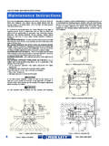
2 To assure long life and perfor-mance of the Planetgear speed reducers, the following practicesshould be Sectional View of a Planetgear Speed BASIC OPERATION AND DESIGNThe Planetgear unit is a concentric shaft speed Reducer that uses asimple planetary design, which utilizes a sun gear as the input, aring gear as the fixed element, and a planetary carrier as the out-put. Power is transmitted from the Reducer input shaft, through asplined connection to the input gear (sun gear) of the first reduc-tion. The input gear drives the planet gears, which in turn drivethe planetary carrier assembly. This carrier assembly is then con-nected to the next reduction sun gear or to the output shaft througha splined connection.
3 Each carrier represents a single Reducer output shaft rotates in the same direction as the inputshaft, regardless of the number of reductions. Reference for a detailed gearing has been made of a high grade alloy steel and casehardened for maximum life. Three to four points of contact, witha minimum of six to eight gear teeth engaged allow for a smoothtransmission of power during normal operation and under extremespike loads. Self contained input and output shaft assemblies SECTIONAL VIEW AND COMPONENT IDENTIFICATIONR eference Figure NAMEPLATE INFORMATIONNote location of serial number and model number on contacting the factory, have the serial number available, asthis unique number fully describes the Reducer and allows for themost efficient and accurate exchange of information.
4 ReferenceFigure for name plate of the Reducer shall not differ from the applicationdata warranted on the nameplate. Any deviations from this datarequires submittal of new application information along with allnameplate data to the factory or service center for approval. Alldata changes require a revised double row of tapered roller bearings mounted to a steel alloyshaft to provide high overhung and thrust load capacity. This fea-ture also keeps all external shaft forces isolated from the in both shaft assemblies are two seals with a grease purge-able cavity between them. This design prevents contaminationfrom entering the gear Reducer under extreme conditions.
5 Theinput shaft assembly also has the ability to add a backstop optionto eliminate Reducer counter rotation when the input driver isshut OperationVenus/ Atlas / Earth /PolarisBullet in #88-PG08 April 1999 NOTES20 Bulletin #88-PG08 April 1999 Venus / Atlas / Earth /PolarisPlanetgear OperationBulletin #88-PG08 April 1999 Section MOUNTING OF TRANSMISSION ACCESSORIESWhen the Planetgear speed Reducer is connected to a motoror driven equipment through the use of couplings, sprockets,gears or belt drives, all rotating parts must be properly guardedwith guarding that conforms to OSHA requirements to pre-vent personal injury or property MOTORS (STANDARD UNITS)When direct coupling motors to the Planetgear Reducer , followthe four step process shown below to achieve proper motor toreducer alignment.
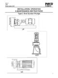
6 Refer to coupling manufacture specificationsto determine required alignment accuracy. Note: Steps 1 to 4may have to be repeated several times to achieve manufacturersrequired #1 ( side view plane )Correct for angular misalignmentin the side view #2 ( side view plane )Correct for parallel misalignmentin the side view #3 ( top view plane )Correct for angular misalignmentin the top view #4 ( top view plane )Correct for parallel misalignmentin the top view avoid personal injury or product damage, never attempt tolift the Reducer with an eyebolt threaded into the top of thereducer all mounting bolts from the Reducer before lifting. Usea double rope sling of ample strength, wrapped around the inputand the output shafts when lifting the speed Reducer ; referenceFigure Reference Table 1 (page 17) for Reducer weights.
7 Besure the Reducer is properly secured and balanced to prevent shift-ing during HANDLING OF REDUCERF igure Reducer HandlingIt is essential that the speed Reducer be securely bolted to a solid,level, and vibration free the Reducer mounting surface is not horizontal, refer to Table 3(page 17) for Maximum Allowable Tilts for Standard Reducer MOUNTINGNOTE: If the Reducer is tilted, the oil requirements may should be of the correct size to fit mounting holes. Theyshould be SAE Grade 5 or equivalent. Fasteners shall be torquedaccording to Table 2 (page 17). The use of a rigid structural steelbaseplate is strongly recommended as a foundation. If a concretefoundation is used, grout structural steel mounting pads into theconcrete rather than grouting the Reducer directly into the con-crete.
8 Allow the concrete to cure before torquing the reducermounting bolts the Reducer with driven equipment by placing broad flatshims underneath all mounting pads of the Reducer . Start at thelow speed end and level across the length and width of the re-ducer. Check with a feeler gauge to make certain there is noclearance and that all pads are supported to prevent distortionof housing when Reducer is bolted down. After the Reducer hasbeen aligned with the driven equipment and bolted down, alignprime mover to the Reducer input shaft. If the Reducer is receivedcoupled to a motor, it has been aligned properly at the , because alignment may have been disturbed duringshipment, it is best to check alignment and then realign if neces-sary.
9 The reliability and long life of the Reducer requires carefulinstallation of accessories and accurate alignment of the connect-ing shafts. Check final alignment of motor shaft, coupling, andreducer shaft after Reducer is in final working SERIAL NUMBERDATE INSTALLEDDATEMAINTENANCE PERFORMEDS ection Log19 Planetgear OperationVenus/ Atlas / Earth /PolarisBullet in #88-PG08 April 1999 Venus / Atlas / Earth /PolarisPlanetgear OperationBulletin #88-PG08 April MOTORS (C-FACE & IEC MOTOR FLANGE UNITS) the Reducer C-face coupling or IEC motor flange cou-pling onto the motor shaft with the appropriate size key. Themotor shaft to coupling fit should be snug and may require lighttapping (Note: Warming up the coupling and applying an Anti-seize compound to the motor shaft is helpful).
10 Note: A loose fitcoupling should be avoided and a heavy fit could damage mo-tor bearings if the coupling is pressed onto the motor shaft withextreme C-FACE: Locate the C-face coupling to inchesfrom the motor face (Hint: Standard 1/2" to 5/8" keystock ishelpful for this purpose). Refer to the illustration in Figure : This dimension changes to to for Venus / Atlas quadruple reductions and Earth / Polaris quintuple IEC MOTOR FLANGE COUPLING: Locate the cou-pling to mm from the motor face. Refer to the illustra-tion in Figure the coupling set screws; one located over the keyand the other located at 90 (degrees). After tightening the setscrews, the gap between the motor face and the coupling shouldbe measured again to insure that the tolerance has been main-tained.